HYDRODYNAMICS OF PUMPS
by Christopher Earls Brennen © Concepts NREC 1994
CHAPTER 7.
CAVITATION AND PUMP PERFORMANCE
7.1 INTRODUCTION
In this chapter we turn our attention to another of the deleterious consequences of cavitation, namely its effect upon the steady state hydraulic performance of a pump. In the next section we present several examples of the effect of cavitation on conventional pumps. This is followed by a discussion of the performance and design of cavitating inducers which are devices added to conventional pumps for the purpose of improving the cavitation performance. Subsequent sections deal with the analytical methods available for the evaluation of cavitation performance and with the thermodynamic effects of the phase change process on that performance.
|
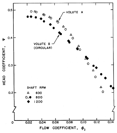
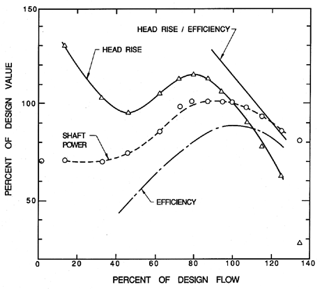
| Figure 7.1 Typical non-cavitating performance for a centrifugal pump, namely Impeller X (see section 2.8) with Volute A and a circular volute of uniform cross-section (from Chamieh 1983). |
7.2 TYPICAL PUMP PERFORMANCE DATA
A typical non-cavitating performance characteristic for a centrifugal pump is shown in figure 7.1 for the Impeller X/Volute A combination (Chamieh 1983) described in section 2.8. The design flow coefficient for this pump is φ2 = 0.092 but we note that it performs reasonably well down to about 30% of this design flow. This flexibility is characteristic of centrifugal pumps. Data is presented for three different shaft speeds, namely 600, 800 and 1200 rpm; since these agree closely we can conclude that there is no perceptible effect of Reynolds number for this range of speeds. The effect of a different volute is also illustrated by the data for Volute B which is a circular volute of circumferentially uniform area. In theory this circular volute is not well matched to the impeller discharge flow and the result is that, over most of the range of flow coefficient, the hydraulic performance is inferior to that with Volute A. However, Volute B is superior at high flow coefficients. This suggests that the flow in Volute A may be more pathological than one would like at these high flow coefficients (see sections 4.4 and 4.6). It further serves to emphasize the importance of a volute (or diffuser) and the need for an understanding of the flow in a volute at both design and off-design conditions.
|
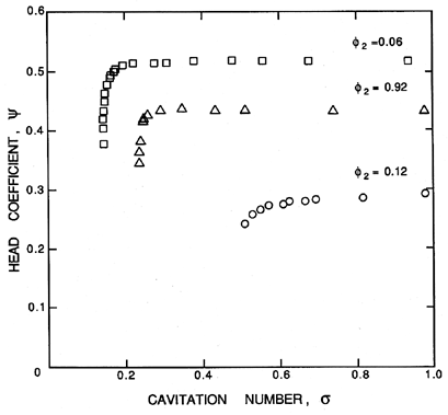
| Figure 7.2 Cavitation performance for the Impeller X/Volute A combination (from Franz et al. 1989, 1990). The flow separation rings of figure 10.17 have been installed so the non-cavitating performance is slightly better than in figure 7.1. |
|
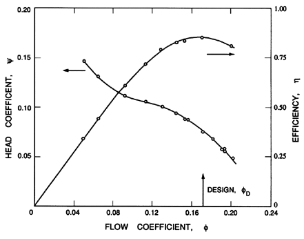
| Figure 7.3 Typical non-cavitating performance characteristics for a 20.3 cm diameter, 3-bladed axial flow pump with a hub-tip ratio, RH/RT, of 0.45 running at about 1500 rpm. At the blade tip the chord is 7.3 cm, the solidity is 0.344 and the blade angle, βbT, is 11.9°. Adapted from Guinard et al. (1953). |
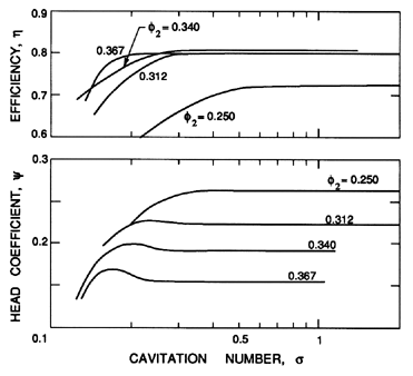
Typical cavitation performance characteristics for a centrifugal pump are presented in figure 7.2 for the Impeller X/Volute A combination. The breakdown cavitation numbers in the range σ=0.1→ 0.4 are consistent with the data in table 5.1. Note that the cavitation head loss occurs more gradually at high flow coefficients than at low values. This is a common feature of the cavitation performance of many pumps, both centrifugal and axial.
|
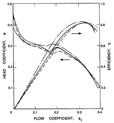
| Figure 7.4 Typical non-cavitating performance characteristics for a four-bladed axial flow pump with tip blade angle, βbT, of about 18°, a hub-tip ratio, RH/RT, of 0.483, a solidity of 0.68 and four different blade profiles (yielding the set of four performance curves). Adapted from Oshima and Kawaguchi (1963). |
Now consider some examples of axial and mixed flow pumps. Typical non-cavitating performance characteristics are shown in figure 7.3 for a Peerless axial flow pump. This unshrouded pump has a design flow coefficient φ2 = 0.171. The maximum efficiency at this design point is about 85%. Axial flow pumps are more susceptible to flow separation and stall than centrifugal pumps and could therefore be considered less versatile. The depression in the head curve of figure 7.3 in the range φ2 = 0.08 → 0.12 is indicative of flow separation and this region of the head/flow curve can therefore be quite sensitive to the details of the blade profile since small surface irregularities can often have a substantial effect on separation. This is illustrated by the data of figure 7.4 which presents the non-cavitating characteristics for four similar axial flow pumps with slightly different blade profiles.
|
| Figure 7.5 Characteristics of a mixed flow pump (Myles 1966). |
|
| Figure 7.6 Head and efficiency characteristics for an axial flow pump with different tip blade angles, βbT (from Peck 1966). |
The kinks in the curves are more marked in this case and differ significantly from one profile to another. Note also that there are small regions of positive slope in the head characteristics. This often leads to instability and to fluctuating pressures and flow rates through the excitation of the surge and stall mechanisms discussed in the following chapters. Sometimes the region of positive slope in the head characteristic can be even more marked as in the example presented in figure 7.5 in which the stall occurs at about 80% of the design flow. As a final example of non-cavitating performance we include in figure 7.6, the effect of the blade angle in an axial flow pump; note that angles of the order of 20° to 30° seem to be optimal for many purposes.
|
| Figure 7.7 Cavitation performance characteristics of the axial flow pump of figure 7.3. Adapted from Guinard et al. (1953). |
|
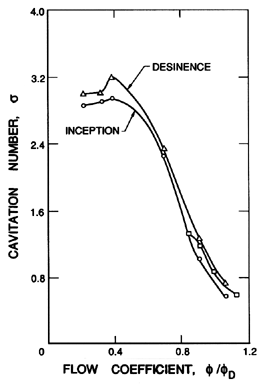
| Figure 7.8 Inception and desinent cavitation numbers (based on wT1) as a function of φ/φD for the axial flow pump of figures 7.3 and 7.7. Adapted from Guinard et al. (1953). |
The cavitation characteristics for some of the above axial flow pumps are presented in figures 7.7 through 7.10. The data of Guinard et al. (1953) provides a particularly well-documented example of the effect of cavitation on an axial flow pump. Note first from figure 7.7 that the cavitation inception number is smallest at the design flow and increases as φ is decreased; the decrease at very low φ does not, however, have an obvious explanation. Since Guinard et al. (1953) noticed the hysteretic effect described in section 5.7 we present figure 7.8 as an example of that phenomenon.
|
| Figure 7.9 Effect of cavitation on the head coefficient and efficiency of one of the axial flow pumps of figure 7.4. The cavitation number is based on wT1. Adapted from Oshima and Kawaguchi (1963). |
|
| Figure 7.10 The critical cavitation number (based on wT1 and 0.5% head loss) for the axial flow pumps of figure 7.4. Adapted from Oshima and Kawaguchi (1963). |
The cavitation data of figure 7.7 also help to illustrate several other characteristic phenomena. Note the significant increase in the head just prior to the decrease associated with breakdown. In the case of the pump tested by Guinard et al., this effect occurs at low flow coefficients. However, other pumps exhibit this phenomenon at higher flows and not at low flows as illustrated by the data of Oshima and Kawaguchi (1963) presented in figure 7.9. The effect is probably caused by an improved flow geometry due to a modest amount of cavitation.
The cavitation data of figure 7.7 also illustrates the fact that breakdown at low flow coefficients occurs at higher cavitation numbers and is usually more abrupt than at higher flow coefficients. It is accompanied by a decrease in efficiency as illustrated by figure 7.9. Finally we include figure 7.10 which shows that the effect of blade profile changes on the head breakdown cavitation number is quite small.
7.3 INDUCER DESIGNS
|
| Figure 7.11 Comparison of the suction specific speed at 3% head drop for process pumps with and without inducer (from Janigro and Ferrini 1973). |
| TABLE 7.1 | |||||||
| Typical rocket engine inducer geometry and performance (from Jakobsen | |||||||
| 1971 and other sources). Key: (a) Main + Partial or Main/Tandem | |||||||
| (b) Radial (RAD), Swept Backwards (SWB) or Swept Forward (SWF) | |||||||
| Rocket: | THOR | J-2 | X-8 | X-8 | J-2 | J-2 | SSME |
| Fluid: | LOX | LOX | LOX | LOX | LH2 | LH2 | LOX |
| No. of Blades (a) | 4 | 3 | 3 | 2 | 4+4 | 4+4 | 4/12 |
| RH1/RT1 | 0.31 | 0.20 | 0.23 | c0.19 | 0.42 | 0.38 | 0.29 |
| RT2/RT1 | 1.0 | 1.0 | c0.9 | c0.8 | 1.0 | c0.9 | 1.0 |
| RH2/RH1 | 1.0 | c2 | c1.5 | 1.5 | c2 | c2 | 2.6 |
| Leading Edge (b) | RAD | SWB | SWB | SWF | SWB | SWB | SWB |
| βbT1 (deg.) | 14.15 | 9.75 | 9.8 | 5.0 | 7.9 | 7.35 | 7.3 |
| φ1D | 0.116 | 0.109 | 0.106 | 0.05 | 0.094 | 0.074 | 0.076 |
| ψ1D | 0.075 | 0.11 | 0.10 | 0.063 | 0.21 | 0.20 | 0.366 |
| N1D | 4.21 | 3.06 | 3.25 | 3.15 | 1.75 | 1.61 | 0.68 |
| αT1 (deg.) | 7.5 | 3.5 | 3.7 | 2.1 | 2.5 | 3.1 | 4.3 |
| σD | 0.028 | 0.021 | 0.025 | 0.007 | 0.011 | 0.011 | |
| SD | 10.4 | 12.5 | 11.4 | 21.2 | 15.8 | 16.2 | |
|
| Figure 7.12 Various geometries of cavitating inducers (from Jakobsen 1971). |
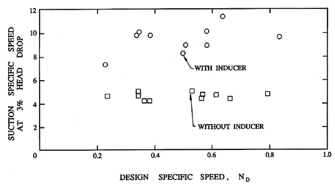
Axial flow inducers are intended to improve the cavitation performance of centrifugal or mixed flow pumps by increasing the inlet pressure to the pump to a level at which it can operate without excessive loss of performance due to cavitation. Typically they consist of an axial flow stage placed just upstream of the inlet to the main impeller. They are designed to operate at small incidence angles and to have thin blades so that the perturbation to the flow is small in order to minimize the production of cavitation and its deleterious effect upon the flow. The objective is to raise the pressure very gradually to the desired level. The typical advantage gained by the addition of an inducer is illustrated in figure 7.11 taken from Janigro and Ferrini (1973). This compares the cavitation performance of a class of process pumps with and without an inducer.
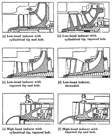
Various types of inducer design are documented in figure 7.12 and in table 7.1, both taken from Jakobsen (1971). Data on the low pressure LOX pump in the Space Shuttle Main Engine (SSME) has been added to table 7.1. Most inducers of recent design seem to be of types (a) or (b). They are unshrouded, with a swept leading edge and often with a forward cant to the blades as in the case of the low pressure LOX pump in the SSME (figure 2.12). This blade cant has the effect of causing the leading edge to be located at a single axial plane counteracting the effect of the sweep given to the leading edge. They are also designed to function at an incidence angle of a few degrees. The reason that the design incidence angle is not zero is that under these conditions cavitation could form on either the pressure or suction surfaces or it could oscillate between the two. It is preferable to use a few degrees of incidence to eliminate this uncertainity and ensure suction surface cavitation.
|
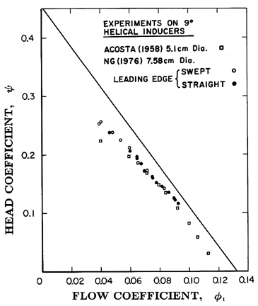
| Figure 7.13 Non-cavitating performance of 9° helical inducers of two different sizes and with and without swept leading edges (the 7.58cm inducers are Impellers III and V). Also shown is the theoretical performance prediction in the absence of losses (from Ng and Brennen 1978). |
|
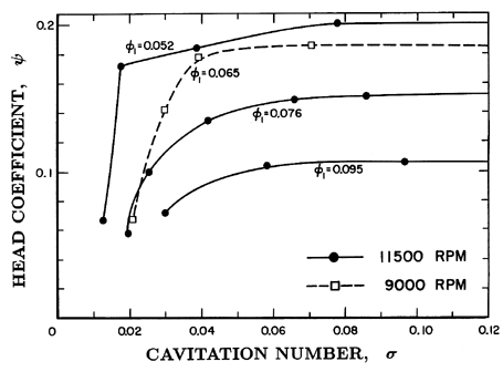
| Figure 7.14 Cavitation performance for Impeller V at various flow coefficients and rotating speeds (from Ng and Brennen 1978). |
|
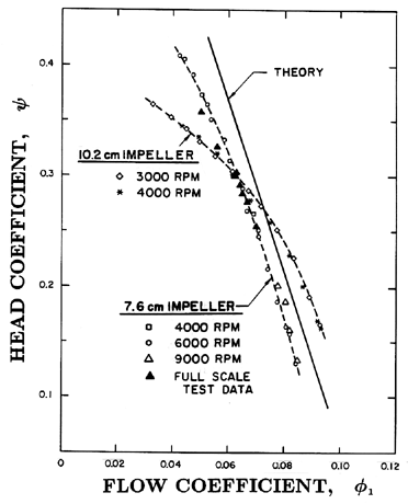
| Figure 7.15 Non-cavitating performance of Impeller IV (7.58cm, with stator) and Impeller VI (10.2cm, without stator) at various rotational speeds. Also shown are full scale test data from Rocketdyne and a theoretical performance prediction (solid line) (from Ng and Brennen 1978). |
Typical inducer performance characteristics are presented in figures 7.13 to 7.16. The non-cavitating performance of simple 9° helical inducers (see figure 2.12) is presented in figure 7.13. The data for the 5.1cm and 7.6cm diameter models appear to coincide indicating very little Reynolds number effect. Furthermore, the non-cavitating performance is the same whether the leading edge is swept or straight. Also included in the figure are the results of the lossless performance prediction of equation 4.6. The agreement with the experiments is about as good as one could expect. It is most satisfactory close to the zero incidence flow coefficient of about 0.09→ 0.10 where one would expect the viscous losses to be a minimum. The comparison also suggests that the losses increase as one either increases or decreases the flow from that zero incidence value.
|
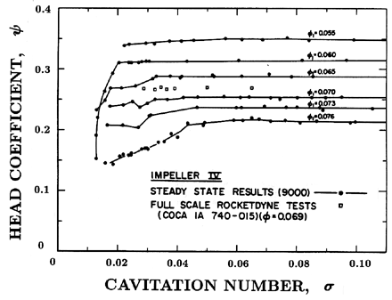
| Figure 7.16 Cavitation performance of Impeller IV at 9000rpm and various flow coefficients. Also shown are full scale test data from Rocketdyne (from Ng and Brennen 1978). |
The cavitation performance of the 7.58cm model of the 9° helical inducer is presented in figure 7.14. These curves for different flow coefficients exhibit the typical pattern of a more gradual head loss at the higher flow coefficients. Notice that the breakdown cavitation number is smaller for non-zero incidence (for example, φ=0.052) than it is for zero incidence (φ=0.095). One would expect the breakdown cavitation number to be a minimum at zero incidence. The fact that the data do not reflect this expectation may be due to the complications at low flow coefficients caused by backflow and the prerotation which backflow induces (see section 4.5).
Another example of inducer performance is presented in figures 7.15 and 7.16, in this case for the SSME low pressure LOX pump model designated Impeller IV (see figure 2.12). In figure 7.15, non-cavitating performance characteristics are shown for two models with diameters of 7.58cm and 10.2cm. The difference in the two characteristics is not related to the size as much as it is to the fact that the 7.58cm model was tested with a set of diffuser (stator) vanes in the axial flow annulus just downstream of the impeller discharge whereas the 10.2cm model was tested without such a diffuser. Note the substantial effect that this has upon the performance. Below the design flow (φ1 approximately 0.076) the stator vanes considerably improve the diffusion process. However, above the design flow, the negative angle of incidence of the flow encountering the stator vanes appears to cause substantial loss and results in degradation of the performance. Some full scale test data (with diffuser) obtained by Rocketdyne is included in figure 7.15 and shows quite satisfactory agreement with the 7.58cm model tests. The results of the theoretical performance given by equation 4.6 are also shown and the comparison between the lossless theory and the experimental data is similar to that of figure 7.13.
The cavitation performance of Impeller IV in water is shown in figure 7.16 along with some data from full scale tests. Note that the head tends to be somewhat erratic at the lower cavitation numbers. Such behavior is typical of most axial flow inducer data and is probably due to hydraulic losses caused by unsteadiness in the flow (see section 8.7).
7.5 EFFECTS OF INDUCER GEOMETRY
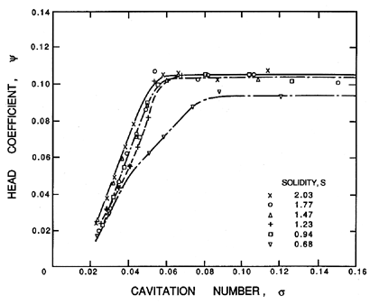
In this section we comment on several geometric factors for which the data suggests optimum values. Clearly, the solidity, s, needs to be as small as possible and yet large enough to achieve the desired discharge flow angle. Data on the effect of the solidity on the performance of a
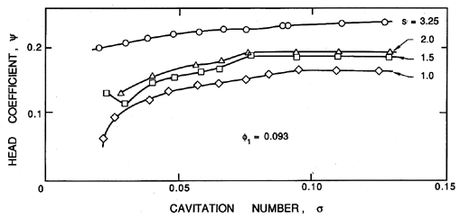
|
| Figure 7.17 The effect of solidity on the cavitation performance of a 9° helical inducer (from Acosta 1958). |
|
| Figure 7.18 The effect of solidity on the cavitation performance of a cavitating inducer (Janigro and Ferrini 1973 from Henderson and Tucker 1962). |
3-bladed, 9° helical inducer has been obtained by Acosta (1958) and on a 4-bladed, 8½° helical inducer by Henderson and Tucker (1962). This data is shown in figures 7.17 and 7.18. The effect on the non-cavitating performance (extreme right of the figures) seems greater for Acosta's inducer than for that of Henderson and Tucker. The latter data suggests that, as expected, the non-cavitating performance is little affected unless the solidity is less than unity. Both sets of data suggest that the cavitating performance is affected more than the non-cavitating performance by changes in the solidity when the latter is less than about unity. Consequently, this data suggests an optimum value of s of about 1.5.
|
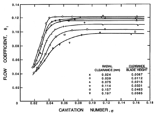
| Figure 7.19 The effect of tip clearance on the cavitation performance of a cavitating inducer (from Henderson and Tucker 1962 as given by Janigro and Ferrini 1973). |
The same two studies also investigated the effect of the tip clearance and the data of Henderson and Tucker (1962) is reproduced in figure 7.19. As was the case with the solidity, the non-cavitating performance is less sensitive to changes in the tip clearance than is the cavitation performance. Note from figure 7.19 that the non-cavitating performance is relatively insensitive to the clearance unless the latter is increased above 2% of the chord when the performance begins to decline more rapidly. The cavitating performance shows a similar dependence though the fractional changes in the performance are larger.
|
| Figure 7.20 Non-cavitating performance of three 9.4° helical inducers with different leading edges as shown. Tests performed with liquid hydrogen (from Moore and Meng 1970b). |
|
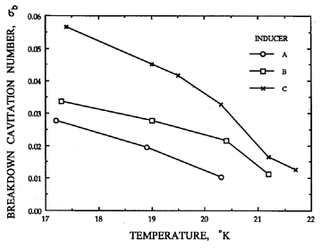
| Figure 7.21 The breakdown cavitation numbers, σb (defined in this case by a 30% head drop) as a function of temperature for three shapes of leading edge (see figure 7.20) on 9.4° helical inducers operating in liquid hydrogen (from Moore and Meng 1970a,b). |
Note that the performance near the knee of the curve indicates an optimum clearance of about 1% of the chord which is in general qualitative agreement with the effect of tip clearance on cavitation inception discussed earlier (see figure 5.20).
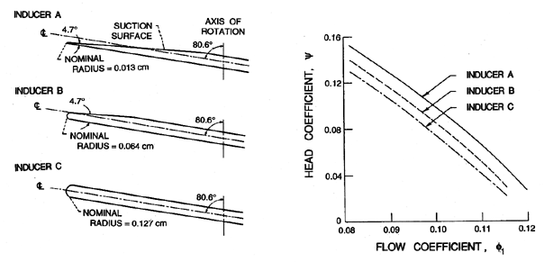
Moore and Meng (1970a,b) have made a study of the effect of the leading edge geometry on inducer performance and their results are depicted graphically in figures 7.20 and 7.21. Note that the leading edge geometry has a significant effect on the non-cavitating performance and on the breakdown cavitation number. Simply stated, the sharper the leading edge the better the hydraulic performance under both cavitating and non-cavitating conditions. There is, however, a trade-off to be made here for very thin leading edges may flutter. This phenomenon is discussed in section 8.12. Incidentally, figure 7.21 also demonstrates the thermal effect on cavitation performance which is discussed in section 7.7.
7.6 ANALYSES OF CAVITATION IN PUMPS
In this and the sections which follow we shall try to give a brief overview of the various kinds of models which have been developed for the analysis of developed cavitation in a pump. Clearly different types of cavitation require different analytical models. We begin in this section with the various attempts which have been made to model traveling bubble cavitation in a pump and to extract from such a model information regarding the damage potential, noise or performance decrement caused by that cavitation. In a later section we shall outline the methods developed for attached blade cavitation. As for the other types of cavitation which are typically associated with the secondary flows ( e.g., tip vortex cavitation, backflow cavitation) there is little that can be added to what has already been described in the last chapter. Much remains to be understood concerning secondary flow cavitation, perhaps because some of the more important effects involve highly unsteady and transient cavitation.
To return to a general discussion of traveling bubble cavitation, it is clear that, given the pressure and velocity distribution along a particular streamline in a reference frame fixed in the impeller, one can input that information into the Rayleigh-Plesset equation 6.1 as discussed in section 6.2. The equation can then be integrated to find the size of the bubble at each point along its trajectory (see examples in section 6.2). Such programs are equally applicable to two-phase flows or to two-component gas/liquid flows.
Since the first applications of the Rayleigh-Plesset equation to traveling bubble cavitation by Plesset (1949) and Parkin (1952) there have been many such investigations, most of which are reviewed by Holl (1969). A notable example is the work of Johnson and Hsieh (1966) who included the motion of the bubble relative to the liquid and demonstrated the possibility of some screening effects because of the motion of the bubbles across streamlines due to centripetal forces. While most of the literature discusses single bubble solutions of this type for flows around simple headforms the same programs can readily be used for the flow around a pump blade provided the pressure distributions on streamlines are known either from an analytic or numerical solution or from experimental measurements of the flow in the absence of cavitation. Such investigations would allow one to examine both the location and intensity of bubble collapse in order to learn more about the potential for cavitation damage.
These methods, however, have some serious limitations. First, the Rayleigh-Plesset equation is only valid for spherical bubbles and collapsing bubbles lose their spherical symmetry as discussed in section 6.4. Consequently any investigation of damage requires considerations beyond those of the Rayleigh-Plesset equation. Secondly, the analysis described above assumes that the concentration of bubbles is sufficiently small so that bubbles do not interact and are not sufficiently numerous to change the flow field from that for non-cavitating flow. This means that they are of little value in predicting the effect of cavitation on pump performance since such an effect implies interactions between the bubbles and the flow field.
It follows that to model the performance loss due to traveling bubble cavitation one must use a two-phase or two-component flow model which implicitly includes interaction between the bubbles and the liquid flow field. One of the first models of this kind was investigated by Cooper (1967) and there have been a number of similar investigations for two-component flows in pumps, for example, that by Rohatgi (1978). While these investigations are useful, they are subject to serious limitations. In particular, they assume that the two-phase mixture is in thermodynamic equilibrium. Such is certainly not the case in cavitation flows where an expression like the Rayleigh-Plesset equation is needed to describe the dynamics of disequilibrium. Nevertheless the models of Cooper and others have value as the first coherent attempts to evaluate the effects of traveling bubble cavitation on pump performance.
Rather than the assumption of thermodynamic equilibrium, two-phase bubble flow models need to be developed in which the bubble dynamics are included through appropriate use of the Rayleigh-Plesset equation. In recent years a number of investigators have employed such models to investigate the dynamics and acoustics of clouds of cavitation bubbles in which the bubbles and the flow interact (see, for example, Chahine 1982, d'Agostino and Brennen 1983, 1989, d'Agostino et al. 1988, Biesheuval and van Wijngaarden 1984, Omta 1987). Among other things these investigations demonstrate that a cloud of bubbles has a set of natural frequencies of its own, separate from (but related to) the bubble natural frequency and that the bubble and flow interaction effects become important when the order of magnitude of the parameter α A2/R2 exceeds unity where α is the void fraction and A and R are the dimensions of the cloud and bubbles respectively. These more appropriate models for travelling bubble cavitation have not, as yet, been used to investigate cavitation effects in pumps.
Several other concepts should be mentioned before we leave the subject of bubbly cavitation in pumps. One such concept which has not received the attention it deserves was put forward by Jakobsen (1964). He attempted to merge the free streamline models (which are discussed later in section 7.8) with his observations that attached cavities on the suction surfaces of impeller blades tend to break up into bubbly mixtures near the closure or reattachment point of the attached cavity. Jakobsen suggested that condensation shocks occur in this bubbly mixture and constitute a mechanism for head breakdown.
|
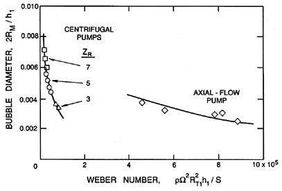
| Figure 7.22 The bubble diameters observed in the blade passages of centrifugal and axial flow pumps as a function of Weber number (adapted from Murakami and Minemura 1978). |
There are also a number of results and ideas that emerge from studies of
the pumping of bubbly gas/liquid mixtures. One of the most important of
these is found in the measurements of bubble size made by
Murakami and Minemura
(1977, 1978). It transpires that, in most practical pumping situations,
the turbulence and shear at inlet tend to break up
all the gas bubbles
larger than a certain size during entry to the blade passages. The ratio
of the force tending to cause fission to the surface tension,  , which
tends to resist fission will be a Weber number and Murakami and Minemura
(1977, 1978) suggest that the ratio of the diameter of the largest bubbles
to survive the inlet shear, 2RM, to the blade spacing, h1, will be a
function of a Weber number, We=ρΩ2 R2T1h1/.
Figure 7.22 presents some data on 2RM/h1 taken by
Murakami and Minemura for both centrifugal and axial flow pumps.
, which
tends to resist fission will be a Weber number and Murakami and Minemura
(1977, 1978) suggest that the ratio of the diameter of the largest bubbles
to survive the inlet shear, 2RM, to the blade spacing, h1, will be a
function of a Weber number, We=ρΩ2 R2T1h1/.
Figure 7.22 presents some data on 2RM/h1 taken by
Murakami and Minemura for both centrifugal and axial flow pumps.
The size of the bubbles in the blade passages is important because it is the migration and coalesence of these bubbles that appears to cause degradation in the performance. Since the velocity of the relative motion between the bubbles and the liquid is proportional to the bubble size raised to some power which depends on the Reynolds number regime, it follows that the larger the bubbles the more likely it is that large voids will form within the blade passage due to migration of the bubbles toward regions of lower pressure (Furuya 1985, Furuya and Maekawa 1985). As Patel and Runstadler (1978) observed during experiments on centrifugal pumps and rotating passages, regions of low pressure occur not only on the suction sides of the blades but also under the shroud of a centrifugal pump. These large voids can cause substantial changes in the deviation angle of the flow leaving the impeller and hence alter the pump performance in a significant way. This mechanism of head degradation is probably significant not only for gas/liquid flows but also for cavitating flows. In gas/liquid flows the higher the velocity the greater the degree of bubble fission at inlet and the smaller the bubbles. But the force acting on the bubbles is also greater for the higher velocity flows and so the net result is not obvious. One can only conclude that both processes, inlet fission and blade passage migration, may be important and deserve further study along the lines begun by Murakami and Minemura.
At the beginning of this section we discussed the application of the Rayleigh-Plesset equation to study the behavior of individual cavitating bubbles. One area in which such an analysis has been useful is in evaluating the differences in the cavitation occurring in different liquids and in the same liquid at different temperatures. These issues will be addressed in the next section. In the subsequent section we turn our attention to the free streamline methods which have been developed to model the flows which occur when large attached cavities or gas-filled voids occur on the blades of a turbomachine.
7.7 THERMAL EFFECT ON PUMP PERFORMANCE
|
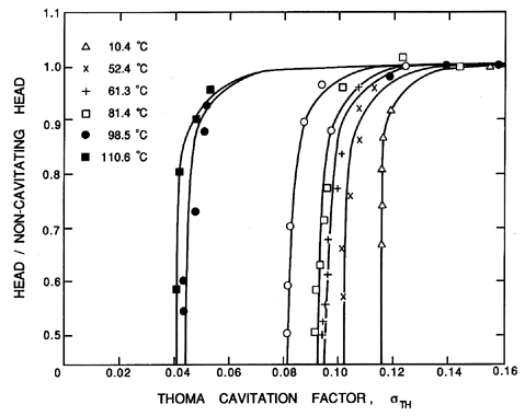
| Figure 7.23 Typical cavitation performance characteristics for a centrifugal pump pumping water at various temperatures as indicated (Arndt 1981 from Chivers 1969). |
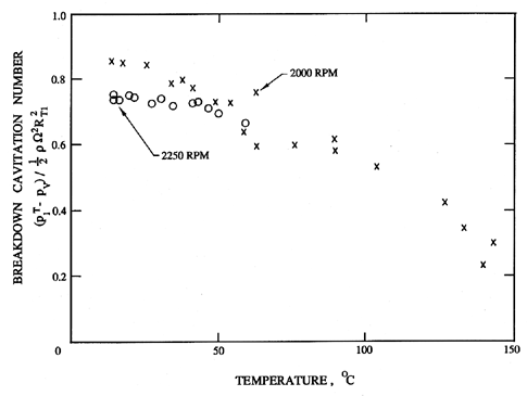
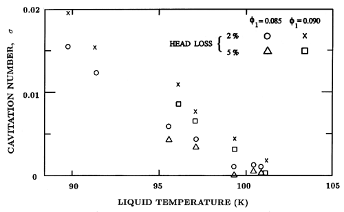
Changes in the temperature of the liquid being pumped will clearly affect the vapor pressure, pV, and therefore the NPSH or cavitation number. This effect has, of course, already been incorporated in the analysis or presentation of the performance by using the difference between the inlet pressure and the vapor pressure rather than the absolute value of the inlet pressure as a flow parameter. But there is another effect of the liquid temperature which is not so obvious and requires some discussion and analysis. It is illustrated by figure 7.23 which includes cavitation performance data for a centrifugal pump (Arndt 1981 from Chivers 1969) operating with water at different inlet temperatures. Note that the cavitation breakdown decreases substantially with increasing temperature. Somewhat counter-intuitively the performance actually improves as the temperature gets greater! The variation of the breakdown cavitation number, σb, with the inlet temperature in Chivers' (1969) experiments is shown in figure 7.24 which includes data for two different speeds and shows a consistent decrease in σb with increasing temperature. The data for the two speeds deviate somewhat at the lowest temperatures. To illustrate that the thermal effect occurs in other liquids and in other kinds of pumps, we include in figure 7.25 data reported by Gross (1973) from tests of the Saturn J-2 liquid oxygen inducer pump. This shows the same pattern manifest in figure 7.24. Other data of this kind has been obtained by Stepanoff (1961), Spraker (1965) and Salemann (1959) for a variety of other liquids.
|
| Figure 7.24 Thermodynamic effect on cavitation breakdown for a commercial centrifugal pump (data from Chivers 1969). |
|
| Figure 7.25 Effect of temperature on the cavitation performance of the J-2 liquid oxygen inducer pump (adapted from Gross 1973). |
The explanation for this effect is most readily given by making reference to traveling bubble cavitation though it can be extended to other forms of cavitation. However, for simplicity, consider a single bubble (or nucleus) which begins to grow when it enters a region of low pressure. Liquid on the surface of the bubble will vaporize to provide the increase in volume of vapor filling the bubble. Consider, now, what happens at two different temperatures, one ``high" and one ``low." At ``low" temperatures the density of the saturated vapor is low and, therefore, the mass rate of evaporation of liquid needed is small. Consequently, the rate at which heat is needed as latent heat to effect this vaporization is low. Since the heat will be conducted from the bulk of the liquid and since the rate of heat transfer is small, this means that the amount by which the temperature of the interface falls below the bulk liquid temperature is also small. Consequently the vapor pressure in the cavity only falls slightly below the value of the vapor pressure at the bulk liquid temperature. Therefore, the driving force behind the bubble growth, namely the difference between the internal pressure (vapor pressure) and the pressure far from the bubble, is not much influenced by thermal effects.
Now, consider the same phenomenon occuring at the ``high'' temperature. Since the vapor density can be many orders of magnitude larger than at the ``low'' temperature, the mass rate of evaporation for the same volume growth rate is much larger. Thus the heat which must be conducted to the interface is much larger which means that a substantial thermal boundary layer builds up in the liquid at the interface. This causes the temperature in the bubble to fall well below that of the bulk liquid and this, in turn, means that the vapor pressure within the bubble is much lower than otherwise might be expected. Consequently, the driving force behind the bubble growth is reduced. This reduction in the rate of bubble growth due to thermal effects is the origin of the thermal effect on the cavitation performance in pumps. Since the cavitation head loss is primarily due to disruption of the flow by volumes of vapor growing and collapsing within the pump, any reduction in the rate of bubble growth will lessen the disruption and result in improved performance.
This thermal effect can be extended to attached or blade cavities with only minor changes in the details. At the downstream end of a blade cavity, vapor is entrained by the flow at a certain volume rate which will depend on the flow velocity and other geometric parameters. At higher temperatures this implies a larger rate of entrainment of mass of vapor due to the larger vapor density. Since vaporization to balance this entrainment is occurring over the surface of the cavity, this implies a larger temperature difference at the higher temperature. And this implies a lower vapor pressure in the cavity than might otherwise be expected and hence a larger ``effective'' cavitation number. Consequently the cavitation performance is improved at the higher temperature.
Both empirical and theoretical arguments have been put forward in attempts to quantify these thermal effects. We shall begin with the theoretical arguments put forward by Ruggeri and Moore (1969) and by Brennen (1973). These explicitly apply to bubble cavitation and proceed as follows.
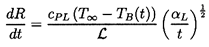
At the beginning of bubble growth, the rate of growth rapidly approaches the value given by equation 6.8 and the important (dR/dt)2 term in the Rayleigh-Plesset equation 6.1 is roughly constant. On the other hand, the thermal term, Θ, which is initially zero, will grow like t½ according to equation 6.6. Consequently there will be a critical time, tC, at which the thermal term, Θ, will approach the magnitude of (pB(T∞)-p)/ρL and begin to reduce the rate of growth. Using the expression 6.6, this critical time is given by
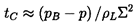 | ......(7.1) |
 | ......(7.2) |
|
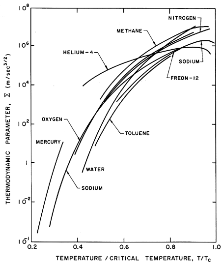
| Figure 7.26 Thermodynamic parameter, Σ, as a function of temperature for various saturated fluids. |
To calculate tC we need values of Σ which by its definition (equation 6.7) is a function only of the liquid temperature. Typical values of Σ for a variety of liquids are presented in figure 7.26 as a function of temperature (the ratio of temperature to critical temperature is used in order to show all the fluids on the same graph). Note that the large changes in the value of Σ are caused primarily by the change in the vapor density with temperature.
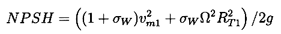
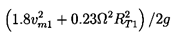
As an example, consider a cavitating flow of water in which the tension, (pB-p), is of the order of 104kg/m s2 or 0.1bar. Then, since water at 20°C has a value of Σ of about 1m/s3/2, the value of tC is of the order of 10 s. Thus, in virtually all pumps, Ωφ will be much greater than 1/tC and no thermal effect will occur. On the other hand at 100°C, the value of Σ for water is about 103 m/s3/2 and it follows that tC = 10μs. Thus in virtually all cases Ω φ « 1/tC and a strong thermal effect can be expected. In fact, in a given application there will exist a ``critical'' temperature above which one should expect a thermal effect on cavitation. For a water pump rotating at 3000rpm this ``critical'' temperature is about 70°C, a value which is consistent with the experimental measurements of pump performance.
The principal difficulty with the above approach is in finding some way to evaluate the tension, pB-p, for use in equation 7.1 in order to calculate tC. Alternatively, the experimental data could be examined for guidance in establishing a criterion based on the above model. To do so equation 7.1 is rewritten in terms of dimensionless groups as follows:
 | ......(7.3) |
 | ......(7.4) |
|
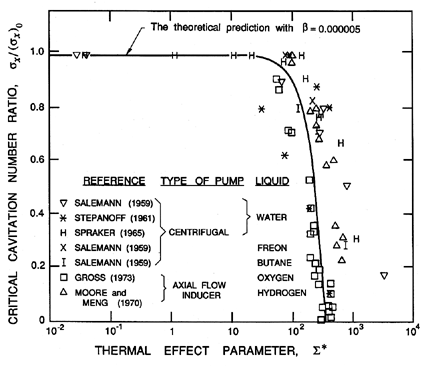
| Figure 7.27 The ratio of the critical cavitation number σx (σa or σb) to (σx)0 (the value of σx in the absence of any thermal effect) as a function of the thermal effect parameter, Σ*. Data is shown for a variety of pumps and liquids. |
(σx)0=-Cpmin and equation 7.4 can be presented in the form
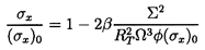 | ......(7.5) |
 | ......(7.6) |
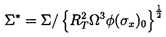
|
| Figure 7.28 The parameter, B′ (in m-1), for several liquids and HT (in m) for centrifugal pumps operating at design flow rate and at a 3% head drop (adapted from Knapp et al. 1970 and Stepanoff 1964). |
A number of purely empirical approaches to the same problem have been suggested in the past. All these empirical methods seek to predict the change in NPSH, say ΔNPSH, due to the thermal effect. This quantity ΔNPSH is the increment by which the cavitation performance characteristic would be shifted to the left as a result of the thermal effect. The method suggested by Stahl and Stepanoff (1956) and Stepanoff (1961, 1964) is widely used; it is based on the premise that the cavitation characteristic of a particular pump operating at a particular speed with two different liquids (or with two different temperatures in the same liquid) would be horizontally shifted by
 | ......(7.7) |
 2
which also occurs in Σ and almost all analyses of the thermal effect.
Then, by examining data from a number of single-stage 3500rpm pumps,
Stahl and Stepanoff arrived at an empirical relation between
HT and the thermodynamic properties of the following form:
2
which also occurs in Σ and almost all analyses of the thermal effect.
Then, by examining data from a number of single-stage 3500rpm pumps,
Stahl and Stepanoff arrived at an empirical relation between
HT and the thermodynamic properties of the following form:
 | ......(7.8) |
The diversity of types of cavitation in a pump and the complexity of the two-phase flow which it generates mean that reliable analytical methods for predicting the cavitating performance characteristics are virtually non-existent. However if the cavity flow can be approximated by single, fully developed or attached cavities on each blade, then this allows recourse to the methods of free streamline theory for which the reader may wish to consult the reviews by Tulin (1964) and Wu (1972) or the books by Birkhoff and Zarantonello (1957) and Brennen (1994). The analytical approaches can be subdivided into linear theories which are applicable to slender, streamlined flows (Tulin 1964) and non-linear theories which are more accurate but can be mathematically much more complex (Wu 1972). Both approaches to free streamline flows have been used in a wide range of cavity flow problems and it is necessary to restrict the present discussion to some of the solutions of relevance to attached cavitation in pumps.
It is instructive to begin by quoting some of the results obtained for single hydrofoils for which the review by Acosta (1973) provides an excellent background. In particular we will focus on the results of approximate linear theories for a partially cavitating or supercavitating flat plate hydrofoil. The partially cavitating solution (Acosta 1955) yields a lift coefficient
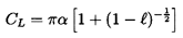 | ......(7.9) |
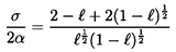 | ......(7.10) |
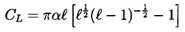 | ......(7.11) |
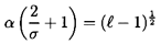 | ......(7.12) |
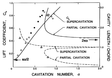
|
| Figure 7.29 Typical results from the linearized theories for a cavitating flat plate at an angle of incidence of 4°. The lift coefficients, CL (solid lines), and the ratios of cavity length to chord, ℓ (dashed lines), are from the supercavitation theory of Tulin (1953) and the partial cavitation theory of Acosta (1955). Also shown are the experimental results of Wade and Acosta (1966) for ℓ (triangles) and for CL (circles) where the open symbols represent points of stable operation and the solid symbols denote points of unstable cavity operation. |
The lift coefficient and the cavity length from equations 7.9 to 7.12 are plotted against cavitation number in figure 7.29 for a typical angle of incidence of α=4°. Note that as σ→∞ the fully wetted lift coefficient, namely 2πα, is recovered from the partial cavitation solution and that as σ→0 the lift coefficient tends to πα/2. Notice also that both the solutions become pathological when the length of the cavity approaches the chord length (ℓ→1). However, if some small portion of each curve close to ℓ=1 were eliminated, then the characteristic decline in the performance of the hydrofoil as the cavitation number is decreased is readily observed. It also compares well with the experimental observations as illustrated by the favorable comparison with the data of Wade and Acosta (1966) included in figure 7.29. Consequently, as the cavitation number is decreased, a single foil exhibits only a small change in the performance or lift coefficient until some critical value of σ (about 0.7 in the case of figure 7.29) is reached. Below this critical value the performance begins to ``breakdown'' quite rapidly. Thus, even a single foil mirrors the typical cavitation performance experienced in a pump. On a more detailed level, note that the small increase in the supercavitating lift coefficient which occurs as the cavitation number is decreased toward the critical value of σ is, in fact, observed experimentally with many single hydrofoils (for example, Wade and Acosta 1966) as well as in some pumps.
The peculiar behaviour of the analytical solutions close to the critical cavitation number is related to an instability which is observed when the cavity length is of the same order as the chord of the foil. However, we delay further discussion of this until the appropriate point in the next chapter (see section 8.10). Some additional data on the variation of the lift coefficient with angle of incidence is included in that later section.
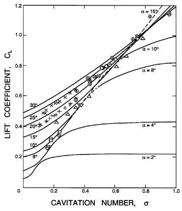
|
| Figure 7.30 Lift coefficients for a flat plate from the non-linear theory of Wu (1962). The experimental data (Parkin 1958) is for angles of incidence as follows: 8° (upsidedown triangles), 10° (squares), 15° (triangles), 20° (circle with plus), 25° (circle with times), and 30° (diamonds). Also shown is some data of Silberman (1959) in a free jet tunnel: 20° (plus) and 25° (times). |
|
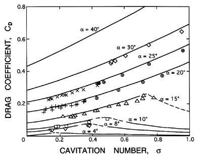
| Figure 7.31 Drag coefficients corresponding to the lift coefficients of figure 7.30. |
Before leaving the subject of the single cavitating foil we should note that more exact, non-linear solutions for a flat plate or an arbitrarily shaped profile have been generated by Wu (1956, 1962), Mimura (1958) and others. As an example of these non-linear results, the lift and drag coefficients at various cavitation numbers and angles of incidence are presented in figures 7.30 and 7.31 where they are compared with the experimental data of Parkin (1958) and Silberman (1959). Data both for supercavitating and partially cavitating conditions are shown in these figures, the latter occurring at the higher cavitation numbers and lower incidence angles (the dashed parts of the curves represent a somewhat arbitrary smoothing through the critical region in which the cavity lengths are close to the chord length). This comparison demonstrates that the non-linear theory yields values which are in good agreement with the experimental measurements. In the case of circular-arc hydrofoils, Wu and Wang (1964) have shown similar agreement with the data of Parkin (1958) for this type of profile. For a recent treatment of supercavitating single foils the reader is referred to the work of Furuya and Acosta (1973).
We now turn to the free streamline analyses which are most pertinent to turbomachines, namely solutions and data for cavitating cascades. Both partially cavitating and supercavitating cascades (see figure 5.10) have been analysed using free streamline methods. Clearly cavities initiated at the leading edge are more likely to extend beyond the trailing edge when the solidity and the stagger angle are small. Such cascade geometries are more characteristic of propellers and, therefore, the supercavitating cascade results are more often applied in that context. On the other hand, most cavitating pumps have large solidities (>1) and large stagger angles. Consequently, partial cavitation is the more characteristic condition in pumps, particularly since the pressure rise through the pump is likely to collapse the cavity before it emerges from the blade passage. In this section we will discuss the supercavitating analyses and data; the next section will deal with the partially cavitating results.
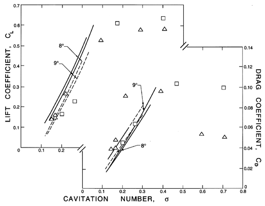
|
| Figure 7.32 Lift and drag coefficients as functions of the cavitation number for cascades of solidity, 0.625, and blade angle, βb=45°+α, operating at angles of incidence, α, of 8° (triangles) and 9° (squares). The points are from the experiments of Wade and Acosta (1967) and the analytical results for a supercavitating cascade are from the linear theory of Duller (1966) (dashed lines) and the non-linear theory of Furuya (1975) (solid lines). |
|
| Figure 7.33 Lift and drag coefficients as functions of the solidity for cascades of blade angle, βb=45°+α, operating at the indicated angles of incidence, α, and at a cavitation number, σ=0.18. The points are from the experiments of Wade and Acosta (1967) and the lines are from the non-linear theory of Furuya (1975). Reproduced from Furuya (1975). |
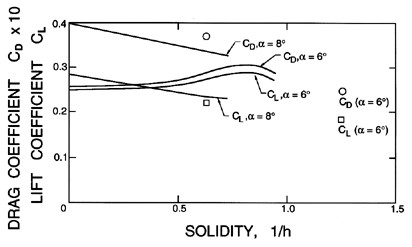
Free streamline methods were first applied to the problems of a cavitating cascade by Betz and Petersohn (1931) who used a linearized method to solve the problem of infinitely long, open cavities produced by a cascade of flat plate hydrofoils. Extensions to this linear, supercavitating solution were generated by Sutherland and Cohen (1958) who solved the problem of finite supercavities behind a flat plate cascade and by Acosta (1960) who generalized this to a cascade of circular arc hydrofoils. Other early contributions to linear cascade theory for supercavitating foils include the models of Duller (1966) and Hsu (1972) and the inclusion of the effect of rounded leading edges by Furuya (1974). Non-linear solutions were first obtained by Woods and Buxton (1966) for the case of a cascade of flat plates. Later Furuya (1975) expanded this work to include foils of arbitrary geometry.
A substantial body of data on the performance of cavitating cascades has been accumulated through the efforts of Numachi (1961, 1964), Wade and Acosta (1967) and others. This allows comparison with the analytical models, in particular the supercavitating theories. Figure 7.32 provides such a comparison between measured lift and drag coefficients (defined as normal and parallel to the direction of the incident stream) for a particular cascade and the theoretical results from the supercavitating theories of Furuya (1975) and Duller (1966). Note that the measured lift coefficients exhibit a clear decline in cascade performance as the cavitation number is reduced and the supercavities grow. However, it is important to observe that this degradation does not occur until the cavitation is quite extensive. The cavitation inception numbers for the experiments were σi=2.35 (for 8°) and σi=1.77 (for 9°). However the cavitation number must be lowered to about 0.5 before the performance is adversely affected. Consequently there is a significant range of intermediate cavitation numbers within which partial cavitation is occurring and within which the performance is little changed.
For the cascades and incidence angles used in the example of figure 7.32, Furuya (1975) shows that the linear and non-linear supercavitation theories yield similar results which are close to those of the experiments. This is illustrated in figure 7.32. However, Furuya also demonstrates that there are circumstances in which the linear theories can be substantially in error and for which the non-linear results are clearly needed. The effect of the solidity on the results is also important because it is a major design factor in determining the number of blades in a pump or propeller. Figure 7.33 illustrates the effect of solidity when large supercavities are present (σ=0.18). Note that the solidity has remarkably little effect at the smaller angles of incidence.
7.10 PARTIALLY CAVITATING CASCADES
In the context of pumps, the solutions by Acosta and Hollander (1959) and Stripling and Acosta (1962) of partial cavitation in a semi-infinite cascade of infinitely thin blades and the solution by Wade (1967) of a finite cascade of partially cavitating foils provide a particularly valuable means of analyzing the performance of two-dimensional cascades with blade cavities. More recently the three dimensional aspects of these solutions have been explored by Furuya (1974). As a complement to purely analytical methods, more heuristic approaches are possible in which the conventional cascade analyses (see sections 3.2, 3.5) are supplemented by lift and drag data for blades operating under cavitating conditions.
|
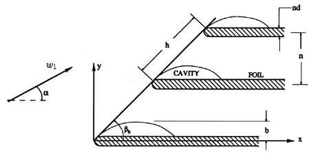
| Figure 7.34 Schematic of partially cavitating cascade of flat blades of thickness nd (Brennen and Acosta 1973). |
Partly for the purposes of example and partly because the results are useful, we shall recount here the results of the free-streamline solution of Brennen and Acosta (1973). This is a slightly modified version of the Acosta and Hollander solution for partial cavitation in a cascade of infinitely thin, flat blades. The modification was to add finite thickness to the blades. As we shall see, this can be important in terms of the relevance of the theory.
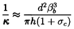
A sketch of the cascade geometry is shown in figure 7.34. A single parameter is introduced to the solution in order to yield finite blade thickness. This parameter implies a ratio, d, of the blade thickness far downstream to the normal spacing between the blades. It also implies a radius of curvature of the parabolic leading edge of the blade, κ, given by
 | ......(7.13) |
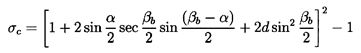
One of the common features of all of these free streamline solutions is that there exists a certain minimum cavitation number at which the cavity becomes infinitely long and below which there are no solutions. This minimum cavitation number is called the choked cavitation number, σc. Were such a flow to occur in practice, it would permit large deviation angles at discharge and a major degradation of performance. Consequently the choked cavitation number, σc, is often considered an approximation to the breakdown cavitation number, σb, for the pump flow which the cascade solution represents. The Brennen and Acosta solution yields a choked cavitation number given by
 | ......(7.14) |
 | ......(7.15) |
 | ......(7.16) |
 | ......(7.17) |
|
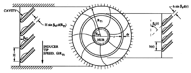
| Figure 7.35 The subdivision of the flow through an axial inducer into radial annuli for cascade analysis. |
|
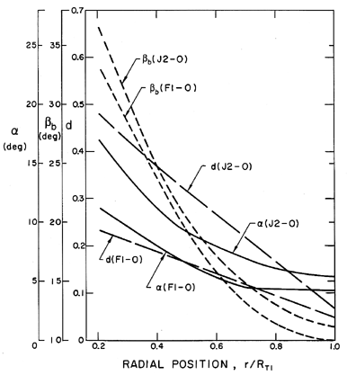
| Figure 7.36 Radial variations of the blade angle, βb, blade thickness to normal spacing ratio, d, and incidence angle α (for φ=0.097) for the oxidizer turbopumps in the Saturn J1 and F1 engines (from Brennen and Acosta 1973). |
|
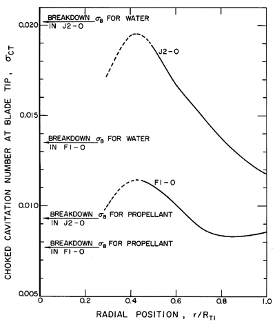
| Figure 7.37 The tip cavitation numbers at which the flow at each radial location becomes choked. Data is shown for the Saturn J2 and F1 oxidizer turbopumps (see figure 7.36); experimentally observed breakdown cavitation numbers in water and propellant are also shown (from Brennen and Acosta 1973). |
|
| Figure 7.38 Radial variations of the blade angle, βb, blade thickness to normal spacing ratio, d, and incidence angle, α, for the 9° helical inducer, Impeller III (from Brennen and Acosta 1976). |
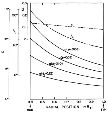
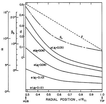
Most pumps or inducer designs incorporate significant variations in α, βb and d over the inlet plane and hence the above analysis has to be performed as a function of the inlet radial position as indicated in figure 7.35. Typical input data for such calculations are shown in figures 7.36, 7.38, and 7.39 for the Saturn J2 and F1 liquid oxygen turbopumps, for the 9° helical inducer, Impeller III, and for the SSME low pressure liquid oxygen impeller, Impeller IV.
|
| Figure 7.39 Radial variations of the blade angle, βb, blade thickness to normal spacing ratio, d, and incidence angle, α, at inlet to the SSME low pressure liquid oxygen pump, Impeller IV (from Brennen and Acosta 1976). |
To proceed with an evaluation of the flow, the cascade at each radial annulus must then be analyzed in terms of the cavitation number, σ(r), pertaining to that particular radius, namely
 | ......(7.18) |
 | ......(7.19) |
| TABLE 7.2 | ||
| Theoretical predictions of breakdown cavitation numbers compared | ||
| with those observed during water tests with various inducer pumps. | ||
| Inducer | Theory σc | Observed σb |
| Saturn J2 Oxidizer Inducer | 0.019 | 0.020 |
| Saturn F1 Oxidizer Inducer | 0.012 | 0.013 |
| SSME Low Pressure LOX Pump | 0.011 | 0.012 |
| 9° Helical Impeller III | 0.009 | 0.012 |
|
| Figure 7.40 The tip cavitation numbers at which the flow at each radial location becomes choked for Impellers III and IV (see figures 7.38 and 7.39) and different flow coefficients, φ1 (from Brennen and Acosta 1976). |
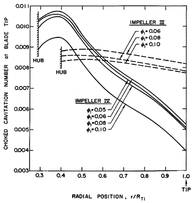
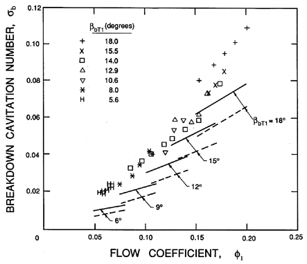
Perhaps the most exhaustive experimental investigation of breakdown cavitation numbers for inducers is the series of experiments reported by Stripling (1962) in which inducers with blade angles at the tip, βbT1, varying from 5.6° to 18°, various leading edge geometries, blade numbers of 3 and 4 and two hub-to-tip ratios were investigated. Some of Stripling's experimental data is presented in figure 7.41 where the σb values are plotted against the flow coefficient, φ1. In his paper Stripling argues that the data correlate with the parameter φ1sinβbT1/(1+cosβbT1) but, in fact, the experimental data are much better correlated with φ1 alone as demonstrated in figure 7.41. There is no satisfactory explanation for the fact that σb correlates better with φ1.
|
| Figure 7.41 The breakdown cavitation numbers for a series of inducers by Stripling (1962) plotted against inlet flow coefficient. The inducers have inlet blade angles at the tip, βbT1 (in degrees), as indicated. Also shown are the results of the cascade analysis (equation 7.15) applied at the rms radius, RRMS, with blade thickness (solid line) and without blade thickness (dashed line). |
Stripling correlates his data with the theoretical values of the choked cavitation number which one would obtain from the above theory in the case of infinitely thin blades. (In this limit the expression for σc is more easily obtained by simultaneous solution of the Bernoulli equation and an equation for the momentum parallel with the blades as Stripling demonstrates.) More specifically, Stripling uses the blade angles, βb1, and incidence angles at the rms radius, RRMS, where
 | ......(7.20) |
Up to this point we have only discussed the calculation of the choked or breakdown cavitation number from the analysis of a partially cavitating cascade. There remains the issue of how to predict the degradation in the head or the cavitation head losses prior to breakdown. The problem here is that calculation of the lift from these analyses produces little for, as one could anticipate, a small partial cavity will not significantly alter the performance of a cascade of higher solidity since the discharge, with or without the cavity, is essentially constrained to follow the direction of the blades. The hydraulic losses which one seeks are additional (or possibly negative) frictional losses generated by the disruption to the flow caused by the cavitation. A number of authors, including Stripling and Acosta (1962), have employed modifications to cascade analyses in order to evaluate the loss of head, ΔH, due to cavitation. One way to view this loss is to recognize that the presence of a cavity in the blade passage causes a reduction in the cross-sectional area available to the liquid flow. When the cavity collapses this area increases creating a ``diffuser'' which is not otherwise present. Hydraulic losses in this ``diffuser'' flow could be considered responsible for the cavitation head loss and could be derived from knowledge of the cavity blockage, b/n.
7.11 CAVITATION PERFORMANCE CORRELATIONS
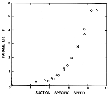
|
| Figure 7.42 Some data on the cavitation head loss parameter, P= ΔH/NPSH, for axial inducer pumps. The two symbols are for two different pumps. |
Finally we provide brief mention of several of the purely empirical methods which are used in practice to generate estimates of the cavitation head loss in pumps. These often consist of an empirical correlation between the cavitation head loss, ΔH, the net positive suction head, NPSH, and the suction specific speed, S. Commonly this correlation is written as
 | ......(7.21) |
 | ......(7.22) |
 | ......(7.23) |
 | ......(7.24) |
 | ......(7.25) |
- Acosta, A.J. (1955). A note on partial cavitation of flat plate hydrofoils. Calif. Inst. of Tech. Hydro. Lab. Rep. E-19.9.
- Acosta, A.J. (1958). An experimental study of cavitating inducers. Proc. Second ONR Symp. on Naval Hydrodyn., ONR/ACR-38, 533--557.
- Acosta, A.J. and Hollander, A. (1959). Remarks on cavitation in turbomachines. Calif. Inst. of Tech. Rep. E-79.3.
- Acosta, A.J. (1960). Cavitating flow past a cascade of circular arc hydrofoils. Calif. Inst. of Tech. Hydro. Lab. Rep. E-79.2.
- Acosta, A.J. (1973). Hydrofoils and hydrofoil craft. Ann. Rev. Fluid Mech., 5, 161--184.
- Arndt, R.E.A. (1981). Cavitation in fluid machinery and hydraulic structures. Ann. Rev. Fluid Mech., 13, 273--328.
- Betz, A. and Petersohn, E. (1931). Application of the theory of free jets. NACA TM No. 667.
- Biesheuvel, A. and van Wijngaarden, L. (1984). Two-phase flow equations for a dilute dispersion of gas bubbles in liquid. J. Fluid Mech., 148, 301--318.
- Birkhoff, G. and Zarantonello, E.M. (1957). Jets, wakes and cavities. Academic Press, NY.
- Brennen, C.E. and Acosta, A.J. (1973). Theoretical, quasistatic analyses of cavitation compliance in turbopumps. J. of Spacecraft and Rockets, 10, No. 3, 175--180.
- Brennen, C.E. (1973). The dynamic behavior and compliance of a stream of cavitating bubbles. ASME J. Fluids Eng., 95, 533--542.
- Brennen, C.E. (1994). Cavitation and bubble dynamics. Oxford Univ. Press.
- Chahine, G.L. (1982). Cloud cavitation theory. Proc. 14th ONR Symp. on Naval Hydrodynamics, 165--194.
- Chamieh, D. (1983). Forces on a whirling centrifugal pump-impeller. Ph.D. Thesis, Calif. Inst. of Tech., and Div. of Eng. and App. Sci. Report No. E249.2.
- Chivers, T.C. (1969). Cavitation in centrifugal pumps. Proc. Inst. Mech. Eng., 184, Part I, No. 2, 37--68.
- Cooper, P. (1967). Analysis of single- and two-phase flows in turbo-pump inducers. ASME J. Eng. Power, 89, 577--588.
- d'Agostino, L. and Brennen, C.E. (1983). On the acoustical dynamics of bubble clouds. ASME Cavitation and Multiphase Flow Forum, 72--75.
- d'Agostino, L., Brennen, C.E., Acosta, A.J. (1988). Linearized dynamics of two-dimensional bubbly and cavitating flows over slender surfaces. J. Fluid Mech., 192, 485--509.
- d'Agostino, L. and Brennen, C.E. (1989). Linearized dynamics of spherical bubble clouds. J. Fluid Mech., 199, 155--176.
- Duller, G.A. (1966). On the linear theory of cascades of supercavitating hydrofoils. U.K. Nat. Eng. Lab. Rep. No. 218.
- Franz, R., Acosta, A.J., Brennen, C.E. and Caughey, T.K. (1989). The rotordynamic forces on a centrifugal pump impeller in the presence of cavitation. Proc. ASME Symp. Pumping Machinery, FED-81, 205--212.
- Franz, R., Acosta, A.J., Brennen, C.E. and Caughey, T.K. (1990). The rotordynamic forces on a centrifugal pump impeller in the presence of cavitation. ASME J. Fluids Eng., 112, 264--271.
- Furuya, O. and Acosta, A.J. (1973). A note on the calculation of supercavitating hydrofoils with rounded noses. ASME J. Fluids Eng., 95, 222--228.
- Furuya, O. (1974). Supercavitating linear cascades with rounded noses. ASME J. Basic Eng., Series D, 96, 35--42.
- Furuya, O. (1975). Exact supercavitating cascade theory. ASME J. Fluids Eng., 97, 419--429.
- Furuya, O. (1985). An analytical model for prediction of two-phase (non-condensable) flow pump performance. ASME J. Fluids Eng., 107, 139--147.
- Furuya, O. and Maekawa, S. (1985). An analytical model for prediction of two-phase flow pump performance -- condensable flow case. ASME Cavitation and Multiphase Flow Forum, FED-23, 74--77.
- Gongwer, C. (1941). A theory of cavitation flow in centrifugal-pump impellers. Trans. ASME, 63, 29--40.
- Gross, L.A. (1973). An experimental investigation of two-phase liquid oxygen pumping. NASA TN D-7451.
- Guinard, P., Fuller, T. and Acosta, A.J. (1953). Experimental study of axial flow pump cavitation. Calif. Inst. of Tech. Hydro. Lab. Report, E-19.3.
- Henderson and Tucker. (1962). Performance investigation of some high speed pump inducers. R.P.E. Tech. Note 214. Reported by Janigro and Ferrini (1973) but not located by the author.
- Holl, J.W. (1969). Limited cavitation. Cavitation State of Knowledge, ASME, 26--63.
- Hsu, C.C. (1972). On flow past a supercavitating cascade of cambered blades. ASME J. Basic Eng., Series D, 94, 163--168.
- Jakobsen, J.K. (1964). On the mechanism of head breakdown in cavitating inducers. ASME J. Basic Eng., 86, 291--304.
- Jakobsen, J.K. (1971). Liquid rocket engine turbopump inducers. NASA SP 8052.
- Janigro, A. and Ferrini, F. (1973). Inducer pumps. In Recent progress in pump research, von Karman Inst. for Fluid Dynamics, Lecture Series 61.
- Johnson, V.E. and Hsieh, T. (1966). The influence of the trajectories of gas nuclei on cavitation inception. Proc. 6th ONR Symp. on Naval Hydrodynamics, 7-1.
- Mimura, Y. (1958). The flow with wake past an oblique plate. J. Phys. Soc. Japan, 13, 1048--1055.
- Moore, R.D. and Meng, P.R. (1970a). Thermodynamic effects of cavitation of an 80.6° helical inducer operated in hydrogen. NASA TN D-5614.
- Moore, R.D. and Meng, P.R. (1970b). Effect of blade leading edge thickness on cavitation performance of 80.6° helical inducers in hydrogen. NASA TN D5855.
- Murakami, M. and Minemura, K. (1977). Flow of air bubbles in centrifugal impellers and its effect on the pump performance. Proc. 6th Australasian Hydraulics and Fluid Mechanics Conf., 1, 382--385.
- Murakami, M. and Minemura, K. (1978). Effects of entrained air on the performance of a horizontal axial-flow pump. In Polyphase Flow in Turbomachinery (editors, C.E. Brennen, P. Cooper and P.W. Runstadler, Jr.), ASME, 171--184.
- Myles, D.J. (1966). A design method for mixed flow pumps and fans. Proc. Symp. on Pump Design, Testing and Operation, Nat. Eng. Lab., Scotland, 167--176.
- Ng, S.L. and Brennen, C.E. (1978). Experiments on the dynamic behavior of cavitating pumps. ASME J. Fluids Eng., 100, No. 2, 166--176.
- Numachi, F. (1961). Cavitation tests on hydrofoils designed for accelerating flow cascade: Report 1. ASME J. Basic Eng., 83, Series D, 637--647.
- Numachi, F. (1964). Cavitation tests on hydrofoils designed for accelerating flow cascade: Report 3. ASME J. Basic Eng., 86, Series D, 543--555.
- Omta, R. (1987). Oscillations of a cloud of bubbles of small and not so small amplitude. J. Acoust. Soc. Amer., 82, 1018--1033.
- Oshima, M. and Kawaguchi, K. (1963). Experimental study of axial and mixed flow pumps. Proc. IAHR Symp. on Cavitation and Hydraulic Machinery, Sendai, Japan, 397--416.
- Parkin, B.R. (1952). Scale effects in cavitating flow. Ph.D. Thesis, Calif. Inst. of Tech., Pasadena.
- Parkin, B.R. (1958). Experiments on circular-arc and flat plate hydrofoils. J. Ship Res., 1, 34--56.
- Patel, B.R. and Runstadler, P.W., Jr. (1978). Investigations into the two-phase flow behavior of centrifugal pumps. In Polyphase Flow in Turbomachinery (eds: C.E. Brennen, P. Cooper and P.W. Runstadler, Jr.), ASME, 79--100.
- Peck, J.F. (1966). Written discussion in Proc. Symp. on Pump Design, Testing and Operation, Nat. Eng. Lab., Scotland, 256--273.
- Plesset, M.S. (1949). The dynamics of cavitation bubbles. Trans. ASME, J. Appl. Mech., 16, 228--231.
- Rohatgi, U.S. (1978). Pump model for two-phase transient flow. In Polyphase Flow in Turbomachinery (eds: C.E. Brennen, P. Cooper and P.W. Runstadler, Jr.), ASME, 101--120.
- Ruggeri, R.S. and Moore, R.D. (1969). Method for prediction of pump cavitation performance for various liquids, liquid temperatures, and rotative speeds. NASA TN D-5292.
- Salemann, V. (1959). Cavitation and NPSH requirements of various liquids. ASME J. Basic Eng., 81, 167--180.
- Silberman, E. (1959). Experimental studies of supercavitating flow about simple two-dimensional bodies in a jet. J. Fluid Mech., 5, 337--354.
- Spraker, W.A. (1965). The effect of fluid properties on cavitation in centrifugal pumps. ASME J. Eng. Power, 87, 309--318.
- Stahl, H.A. and Stepanoff, A.J. (1956). Thermodynamic aspects of cavitation in centrifugal pumps. Trans. ASME, 78, 1691--1693.
- Stepanoff, A.J. (1961). Cavitation in centrifugal pumps with liquids other than water. ASME J. Eng. Power, 83, 79--90.
- Stepanoff, A.J. (1964). Cavitation properties of liquids. ASME J. Eng. Power, 86, 195--200.
- Stripling, L.B. and Acosta, A.J. (1962). Cavitation in turbopumps - Part I. ASME J. Basic Eng., 84, 326--338.
- Stripling, L.B. (1962). Cavitation in turbopumps - Part II. ASME J. Basic Eng., 84, 339--350.
- Sutherland, C.D. and Cohen, H. (1958). Finite cavity cascade flow. Proc. 3rd U.S. Nat. Cong. of Appl. Math., 837--845.
- Tulin, M.P. (1953). Steady two-dimensional cavity flows about slender bodies. David Taylor Model Basin Rep. 834.
- Tulin, M.P. (1964). Supercavitating flows - small perturbation theory. J. Ship Res., 7, No. 3, 16--37.
- Wade, R.B. and Acosta, A.J. (1966). Experimental observations on the flow past a planoconvex hydrofoil. ASME J. Basic Eng., 88, 273--283.
- Wade, R.B. (1967). Linearized theory of a partially cavitating cascade of flat plate hydrofoils. Appl. Sci. Res., 17, 169--188.
- Wade, R.B. and Acosta, A.J. (1967). Investigation of cavitating cascades. ASME J. Basic Eng., Series D, 89, 693--706.
- Woods, L.C. and Buxton, G.H.L. (1966). The theory of cascade of cavitating hydrofoils. Quart. J. Mech. Appl. Math., 19, 387--402.
- Wu, T.Y. (1956). A free streamline theory for two-dimensional fully cavitated hydrofoils. J. Math. Phys., 35, 236--265.
- Wu, T.Y. (1962). A wake model for free streamline flow theory, Part 1. Fully and partially developed wake flows and cavity flows past an oblique flat plate. J. Fluid Mech., 13, 161--181.
- Wu, T.Y. and Wang, D.P. (1964). A wake model for free streamline flow theory, Part 2. Cavity flows past obstacles of arbitrary profile. J. Fluid Mech., 18, 65--93.
- Wu, T.Y. (1972). Cavity and wake flows. Ann. Rev. Fluid Mech., 4, 243--284.
Last updated 12/1/00.
Christopher E. Brennen