HYDRODYNAMICS OF PUMPS
by Christopher Earls Brennen © Concepts NREC 1994
CHAPTER 3.
TWO-DIMENSIONAL PERFORMANCE ANALYSIS
3.1 INTRODUCTION
In this and the following chapter, we briefly survey the more detailed analyses of the flow in axial and centrifugal pumps, and provide a survey of some of the models used to synthesize the noncavitating performance of these turbomachines. The survey begins in this chapter with a summary of some of the results that emerge from a more detailed analysis of the two-dimensional flow in the meridional plane of the turbomachine, while neglecting most of the three-dimensional effects. In this regard, sections 3.2 through 3.4 address the analyses of linear cascades for axial flow machines, and section 3.5 summarizes the analyses of radial cascades for centrifugal machines. Three-dimensional effects are addressed in the next chapter.
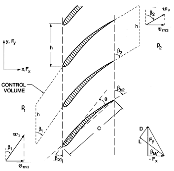
The fluid mechanics of a linear cascade will now be examined in more detail, so that the role played by the geometry of the blades and information on the resulting forces on individual blades may be used to supplement the analysis of section 2.7. Referring to the periodic control volume indicated in figure 3.1, and applying the momentum theorem to this control volume, the forces, Fx and Fy, imposed by the fluid on each blade (per unit depth normal to the sketch), are given by
 | ......(3.1) |
 | ......(3.2) |
|
| Figure 3.1 Schematic of a linear cascade showing the blade geometry, the periodic control volume and the definition of the lift, L, and drag, D, forces on a blade. |
To proceed, we define the vector mean of the relative velocities, w1 and w2, as having a magnitude wm and a direction βm, where by simple geometry
 | ......(3.3) |
 | ......(3.4) |
 | ......(3.5) |
 | ......(3.6) |
 | ......(3.7) |
 | ......(3.8) |
 | ......(3.9) |
 | ......(3.10) |
 | ......(3.11) |
Also note that equations 3.1 through 3.9 yield the head/flow characteristic given by
 | ......(3.12) |
 | ......(3.13) |
 | ......(3.14) |
|
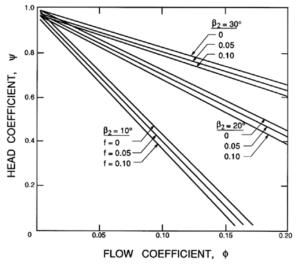
| Figure 3.2 Calculated head/flow characteristics for some linear cascades. |
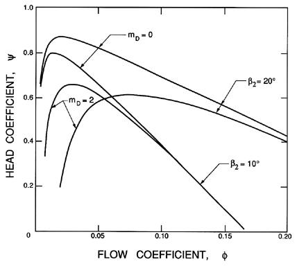
Figure 3.2 presents examples of typical head/flow characteristics resulting from equation 3.13 for some chosen values of β2 and the friction coefficient, f. It should be noted that, in any real turbomachine, f will not be constant but will vary substantially with the flow coefficient, φ, which determines the angle of incidence and other flow characteristics. More realistic cases are presented a little later in figure 3.3.
The observant reader will have noted that all of the preceding equations of this section involve only the inclinations of the flow and not of the blades, which have existed only as ill-defined objects that achieve the turning of the flow. In order to progress further, it is necessary to obtain a detailed solution of the flow, one result of which will be the connection between the flow angles (βm, β2) and the geometry of the blades, including the blade angles (βb, βb1, βb2). A large literature exists describing methods for the solutions of these flows, but such detail is beyond the scope of this text. As in most high Reynolds number flows, one begins with potential flow solutions, for which the reader should consult a modern text, such as that by Horlock (1973), or the valuable review by Roudebush (1965). König (1922) produced one of the earliest potential flow solutions, namely that for a simple flat plate cascade of infinitely thin blades. This was used to generate figure 3.4. Such potential flow methods must be supplemented by viscous analyses of the boundary layers on the blades and the associated wakes in the discharge flow. Leiblein (1965) provided an excellent review of these viscous flow methods, and some of his basic methodology will be introduced later.
To begin with, however, one can obtain some useful insights by employing our basic knowledge and understanding of lift and drag coefficients obtained from tests, both those on single blades (airfoils, hydrofoils) and those on cascades of blades. One such observation is that the lift coefficient, CL, is proportional to the sine of the angle of attack, where the angle of attack is defined as the angle between the mean flow direction, βm, and a mean blade angle, βbM. Thus
 | ......(3.15) |
 | ......(3.16) |
 | ......(3.17) |
|
| Figure 3.3 Calculated head/flow characteristics for a linear cascade using blade drag coefficients given by equation 3.18 with CD0=0.02. The corresponding characteristics with CD0=mD=0 are shown in figure 3.2. |
It is also useful to consider the drag coefficient, CD, for it clearly defines f and the viscous losses in the cascade. Instead of being linear with angle of attack, CD will be an even function so an appropriate empirical result corresponding to equation 3.15 would be
 | ......(3.18) |
3.3 DEVIATION ANGLE
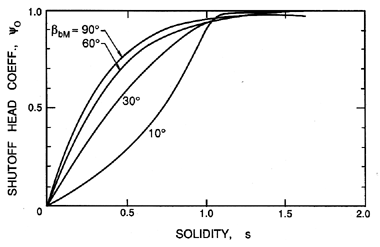
While the simple, empirical approach of the last section has practical and educational value, it is also valuable to consider the structure of the flow in more detail, and to examine how higher level solutions to the flow might be used to predict the performance of a cascade of a particular geometry. In doing so, it is important to distinguish between performance characteristics that are the result of idealized inviscid flow and those that are caused by viscous effects. Consider, first, the inviscid flow effects. König (1922) was the first to solve the potential flow through a linear cascade, in particular for a simple cascade of infinitely thin, straight blades. The solution leads to values of the deviation, δ, that, in turn, allow evaluation of the shut-off head coefficient, ψ0, through equation 3.17. This is shown as a function of solidity in figure 3.4. Note that for solidities greater than about unity, the idealized, potential flow exits the blade passages parallel to the blades, and hence ψ0 → 1.
|
| Figure 3.4 The performance parameter, ψ0, as a function of solidity, s, for flat plate cascades with different blade angles, βb. Adapted by Wislicensus (1947) (see also Sabersky, Acosta and Hauptmann 1989) from the potential flow theory of König (1922). |
Another approach to the same issue of relating the flow angle, β2, to the blade angles, is to employ an empirical rule for the deviation angle, δ=βb2-β2 (equation 2.2), in terms of other geometric properties of the cascade. One early empirical relation suggested by Constant (1939) (see Horlock 1973) relates the deviation to the camber angle, θc, and the solidity, s, through
 | ......(3.19) |
3.4 VISCOUS EFFECTS IN LINEAR CASCADES
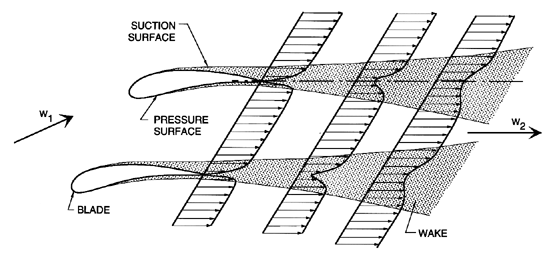
It is also of value to examine in more detail the mechanism of viscous loss in a cascade. Even in two-dimensional cascade flow, the growth of the boundary layers on the pressure and suction surfaces of the blades, and the wakes they form downstream of the blades (see figure 3.5), are complex, and not amenable to simple analysis.
|
| Figure 3.5 Sketch of the boundary layers on the surfaces of a cascade and the resulting blade wakes. |
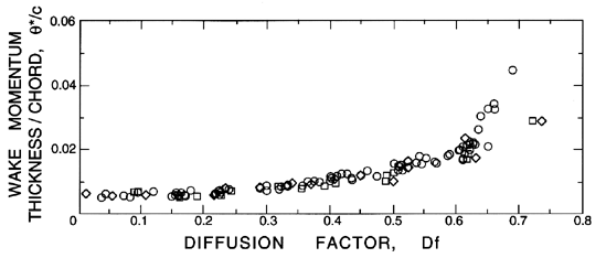
However, as the reviews by Roudebush and Lieblein (1965) and Lieblein (1965) demonstrate, it is nevertheless possible to provide some qualitative guidelines for the resulting viscous effects on cascade performance. In this respect, the diffusion factor, introduced by Lieblein et al. (1953), is a useful concept that is based on the following approximations. First, we note that under normal operating conditions, the boundary layer on the suction surface will be much thicker than that on the pressure surface of the foil, so that, to a first approximation, we may neglect the latter. Then, the thickness of the wake (and therefore the total pressure loss) will be primarily determined by that fraction of the suction surface over which the velocity gradient is adverse, since that is where the majority of the boundary layer growth occurs. Therefore, Lieblein et al. argued, the momentum thickness of the wake, θ*, should correlate with a parameter they termed the diffusion factor, given by (wmax-w2)/wmax, where wmax is the maximum velocity on the suction surface. One should visualize deceleration or diffusion of the flow from wmax to w2, and that this diffusion is the primary factor in determining the wake thickness. However, since wmax is not easily determined, Lieblein et al. suggest an approximation to the diffusion factor that is denoted Df, and given by
 | ......(3.20) |
|
| Figure 3.6 Correlation of the ratio of the momentum thickness of the blade wakes, θ*, to the chord, c, with the diffusion factor, Df, for cascades of blades with three different profiles: NACA 65-(A10)10 series (circles) and two British C.4 parabolic arc profiles (squares and diamonds). The maximum thickness of the blades is 0.1c and the Reynolds number is 2.5 × 10⁵. Adapted from Lieblein (1965). |
Note that, once θ*/c has been determined from such a correlation, the drag coefficient, CD, and the friction or loss coefficient follow from equations 3.7, 3.9, and 3.10 and the fact that D=ρ w22 θ*:
 | ......(3.21) |
In an actual turbomachine, there are several additional viscous loss mechanisms that were not included in the cascade analyses discussed above. Most obviously, there are additional viscous layers on the inner and outer surfaces that bound the flow, the hub and the shroud (or casing). These often give rise to complex, three-dimensional secondary flows that lead to additional viscous losses (Horlock and Lakshminarayana 1973). Moreover, the rotation of other, ``non-active'' surfaces of the impeller will lead to viscous shear stresses, and thence to losses known as ``disk friction losses'' in the terminology of turbomachines. Also, leakage flows from the discharge back to the suction, or from one stage back to a preceding stage in a multistage pump, constitute effective losses that must be included in any realistic evaluation of the losses in an actual turbomachine (Balje 1981).
|
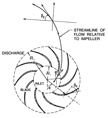
| Figure 3.7 Schematic of the radial cascade corresponding to the linear cascade of figure 3.1. |
Two-dimensional models for centrifugal or radial turbomachines begin with analyses of the flow in a radial cascade (section 2.2 and figure 3.7), the counterpart of the linear cascade for axial flow machines. More specifically, the counterpart of the linear flat plate cascade is the logarithmic spiral cascade, defined in section 2.2, and shown in more detail in figure 3.7. There exist simple conformal mappings that allow potential flow solutions for the linear cascade to be converted into solutions for the corresponding radial cascade flow, though the proper interpretation of these solutions requires special care. The resulting head/flow characteristic for frictionless flow in a radial cascade of infinitely thin logarithmic spiral blades is given in a classic paper by Busemann (1928), and takes the form
 | ......(3.22) |
However, it is important to recognize that the ψ0 term is the result of a frictionless, potential flow solution in which the vorticity is zero. This solution would be directly applicable to a static or nonrotating radial cascade in which the flow entering the cacade has no component of the vorticity vector in the axial direction. This would be the case for a nonswirling axial flow that is deflected to enter a nonrotating, radial cascade in which the axial velocity is zero. But, relative to a rotating radial cascade (or centrifugal pump impeller), such an inlet flow does have vorticity, specifically a vorticity with magnitude 2Ω and a direction of rotation opposite to the direction of rotation of the impeller. Consequently, the frictionless flow through the impeller is not irrotational, but has a constant and uniform vorticity of -2Ω.
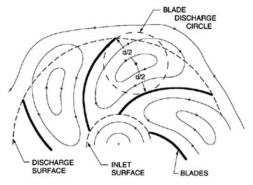
In inviscid fluid mechanics, one frequently obtains solutions for these kinds of rotational flows in the following way. First, one obtains the solution for the irrotational flow, which is represented by ψ0 in the current problem. Mathematically, this is the complementary solution. Then one adds to this a particular solution that satisfies all the same boundary conditions, but has a uniform vorticity, -2Ω. In the present context, this particular, or rotational, solution leads to the term, Sfb, which, therefore, has a quite different origin from the irrotational term, ψ0. The division into the rotational solution and the irrotational solution is such that all the net volumetric flow through the impeller is included in the irrotational (or ψ0) component. The rotational solution has no through flow, but simply consists of a rotation of the fluid within each blade passage, as sketched in figure 3.8.
|
| Figure 3.8 A sketch of the displacement component of the inviscid flow through a rotating radial cascade. |
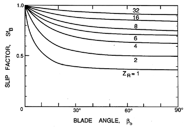
Busemann (1928) called this the displacement flow; other authors refer to its rotating cells as relative eddies (Balje 1980, Dixon 1978). In his pioneering work on the fluid mechanics of turbomachines, Stodola (1927) was among the first to recognize the importance of this rotational component of the solution. Busemann (1928) first calculated its effect upon the head/flow characteristic for the case of infinitely thin, logarithmic spiral blades, in other words the simple cascade in the radial configuration. For reasons which will become clear shortly, the function, Sfb, is known as the Busemann slip factor, and Busemann's solutions lead to the values presented in figure 3.9 when the solidity, s > 1.1.
|
| Figure 3.9 The Busemann slip factor, Sfb, plotted against the blade angle, βb, for various numbers of blades, ZR. The results shown are for radial cascades of infinitely thin logarithmic spiral blades with solidities, s > 1.1. Adapted by Sabersky, Acosta and Hauptmann (1989) and Wislicenus (1947) from Busemann's (1928) theory. |
Note that the values of Sfb are invariably less than or equal to unity, and, therefore, the effect of the displacement flow is to cause a decrease in the head. This deficiency can, however, be minimized by using a large number of blades. As the number of blades gets larger, Sfb tends to unity as the rotational flow within an individual blade passage increasingly weakens. In practice, however, the frictional losses will increase with the number of blades. Consequently, there is an important compromise that must be made in choosing the number of blades. As figure 3.9 shows, this compromise will depend on the blade angle. Furthermore, the compromise must also take into account the structural requirements for the blades. Thus, radial machines for use with liquids usually have a smaller number of blades than those used for gases. The reason for this is that a liquid turbomachine requires much thicker blades, and, therefore, each blade creates much more flow blockage than in the case of a gas turbomachine. Consequently, liquid machines tend to have a smaller number of blades, typically eight for the range of specific speeds for which radial machines are designed (ND<1.5) (Stepanoff 1948, Anderson). Another popular engineering criterion (Stepanoff 1948) is that ZR should be one third of the discharge blade angle, βb (in degrees).
The decrease in the head induced by the displacement flow is due to the nonuniformity in the discharge flow; this nonuniformity results in a mean angle of discharge (denoted by β2) that is different from the discharge blade angle, βb2, and, therefore, implies an effective deviation angle or slip, Sf (see section 2.1). In fact, it is clear that the relations 2.16, 2.32, 3.22, and 2.4 imply that Sf=Sfb, and, hence, the terminology used above. Stodola (1927) recognized that slip would be a consequence of the displacement flow, and estimated the magnitude of the slip velocity, vθ s, in the following approximate way. He argued that the slip velocity could be roughly estimated as Ω d/2, where d/2 is the radius of the blade discharge circle shown in figure 3.8. He visualized this as representative of the rotating cell of fluid in a blade passage, and that the rotation of this cell at Ω would lead to the aforementioned vθ s. Then, provided ZR is not too small, d is approximately equal to 2π R2 sin βb2, and it follows that
 | ......(3.23) |
 | ......(3.24) |
There is a substantial literature on slip factors for centrifugal pumps. Some of this focuses on the calculation of slip factors for inviscid flow in radial cascades with blades that are more complex than the infinitely thin, logarithmic spiral blades used by Busemann. Useful reviews of some of this work can be found, for example, in the work of Wislicenus (1947), Stanitz (1952), and Ferguson (1963). Other researchers attempt to find slip factors that provide the best fit to experimental data. In doing so, they also attempt to account for viscous effects in addition to the inviscid effect for which the slip factor was originally devised. As an example of this approach, the reader may consult Wiesner (1967), who reviews the existing, empirical slip factors, and suggests one that seems to yield the best comparison with the experimental measurements.
3.6 VISCOUS EFFECTS IN RADIAL FLOWS
We now turn to a discussion of the viscous effects in centrifugal pumps. Clearly a radial cascade will experience viscous boundary layers on the blades that are similar to those discussed earlier for axial flow machines (see section 3.4). However, two complicating factors tend to generate loss mechanisms that are considerably more complicated. These two factors are flow separation and secondary flow.
|
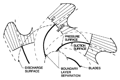
| Figure 3.10 A sketch of actual discharge flow from a centrifugal pump or compressor including the alternating pattern of jets and wakes resulting from flow separation from the suction surfaces. |
Normally, the flow in a centrifugal pump separates from the suction surface near the leading edge, and produces a substantial wake on the suction surfaces of each of the blades. Fischer and Thoma (1932) first identified this phenomenon, and observed that the wake can occur even at design flow. Normally, it extends all the way to the impeller discharge. Consequently, the discharge flow consists of a low velocity zone or wake next to the suction surface, and, necessarily, a flow of increased velocity in the rest of the blade passage. This ``jet-wake structure'' of the discharge is sketched in figure 3.10. Note that this viscous effect tends to counteract the displacement flow of figure 3.8. Since the work of Fischer and Thoma, many others have studied this aspect of flows in centrifugal pumps and compressors (see, for example, Acosta and Bowerman 1957, Johnston and Dean 1966, Eckardt 1976), and it is now recognized as essential to take these features into account in constructing any model of the flow in radial turbomachines. Modern analyses of the flow in radial turbomachines usually incorporate the basic features of the jet-wake structure in the blade passages (for example, Sturge and Cumpsty 1975, Howard and Osborne 1977). Sturge and Cumpsty have calculated the shape of the wake in a typical, two-dimensional radial cascade, using numerical methods to solve a free streamline problem similar to those discussed in chapter 7.
At design flow, the wake or boundary layer on the suction surface may be quite thin, but as the flow coefficient, φ, is decreased, the increased incidence leads to larger wakes (Fischer and Thoma 1932, Johnston and Dean 1966). Clearly, the nonuniformity of the discharge flow implies an ``effective'' slip due to these viscous effects. This slip will not only depend on the geometry of the blades but will also be a function of the flow coefficient and the Reynolds number. The change with flow coefficient is particularly interesting. As φ is decreased below the design value and the wake grows in width, an increasing fraction of the flow is concentrated in the jet. Johnston and Dean (1966) showed that this results in a flow that more closely follows the geometry of the pressure surface, and, therefore, to a decrease in the slip. This can be a major effect in radial compressors. Johnston and Dean made measurements in an 18-bladed radial compressor impeller with a 90° discharge blade angle (for which SfS=0.825), and found that the effective slip factor increased monotonically from a value of about 0.8 at φ2=0.5 to a value of 1.0 at φ2=0.15. However, this increase in the slip factor did not produce an increase in the head rise, because the increase in the viscous losses was greater than the potential gain from the decrease in the slip.
Finally, it is important to recognize that secondary flows can also have a substantial effect on the development of the blade wakes, and, therefore, on the jet-wake structure. Moreover, the geometric differences between the typical radial compressor and the typical centrifugal pump can lead to significant differences in the secondary flows, the loss mechanisms, and the jet-wake structure. The typical centrifugal pump geometry was illustrated in figure 2.7, to which we should append the typical number of blades, ZR=8. A typical example is the geometry at ND=0.6, namely RT1/RT2=0.5 and B2=0.2RT2. Assuming ZR=8 and a typical blade angle at discharge of 25°, it follows that the blade passage flow at discharge has cross-sectional dimensions normal to the relative velocity vector of 0.2RT2 × 0.3RT2, while the length of the blade passage is approximately 1.2RT2. Thus the blade passage is fairly wide relative to its length. In contrast, the typical radial compressor has a much smaller value of B2/RT2, and a much larger number of blades. As a result, not only is the blade passage much narrower relative to its length, but also the typical cross-section of the discharge flow is far from square, being significantly narrower in the axial direction. The viscous boundary layers on the suction and pressure surfaces of the blades, and on the hub and shroud (or casing), will have a greater effect the smaller the cross-sectional dimensions of the blade passage are relative to its length. Moreover, the secondary flows that occur in the corners of this passage amplify these viscous effects. Consequently, the flow that discharges from a blade passage of a typical radial compressor is more radically altered by these viscous effects than the flow discharging from a typical centrifugal pump.
- Acosta, A.J. and Bowerman, R.D. (1957). An experimental study of centrifugal pump impellers. Trans. ASME, 79, 1821--1839.
- Anderson, H.H. (Undated). Centrifugal pumps. The Trade and Technical Press Ltd., Crown House, Morden, England.
- Balje, O.E. (1981). Turbomachines. A guide to design, selection and theory. John Wiley and Sons, New York.
- Busemann, A. (1928). Das Förderhöhenverhältnis radialer Kreiselpumpen mit logarithmisch-spiraligen Schaufeln. Z. angew. Math. u. Mech., 8, 372.
- Constant, H. (1939). Performance of cascades of aerofoils. Royal Aircraft Est. Note No. E3696 and ARC Rep. No. 4155.
- Dixon, S.L. (1978). Fluid mechanics, thermodynamics of turbomachinery. Pergamon Press.
- Eckardt, D. (1976). Detailed flow investigations with a high-speed centrifugal compressor impeller. ASME J. Fluids Eng., 98, 390--420.
- Ferguson, T.B. (1963). The centrifugal compressor stage. Butterworth, London.
- Fischer, K. and Thoma, D. (1932). Investigation of the flow conditions in a centrifugal pump. Trans. ASME, Hydraulics, 54, 141--155.
- Horlock, J.H. (1973). Axial flow compressors. Robert E. Krieger Publ. Co., New York.
- Horlock, J.H. and Lakshminarayana, B. (1973). Secondary flows: theory, experiment and application in turbomachinery aerodynamics. Ann. Rev. Fluid Mech., 5, 247--279.
- Howard, J.H.G. and Osborne, C. (1977). A centrifugal compressor flow analysis employing a jet-wake passage model. ASME J. Fluids Eng., 99, 141--147.
- Howell, A.R. (1942). The present basis of axial flow compressor design: Part I---Cascade theory and performance. ARC R and M No. 2095.
- Johnston, J.P. and Dean, R.C. (1966). Losses in vaneless diffusers of centrifugal compressors and pumps. ASME J. Eng. for Power, 88, 49--62.
- König, E. (1922). Potentialströmung durch Gitter. Z. angew. Math. u. Mech., 2, 422.
- Lieblein, S., Schwenk, F.C., and Broderick, R.L. (1953). Diffusion factor for estimating losses and limiting blade loadings in axial-flow-compressor blade elements. NACA RM E53D01.
- Lieblein, S. (1965). Experimental flow in two-dimensional cascades. Aerodynamic design of axial flow compressors, NASA SP-36, 183--226.
- Roudebush, W.H. (1965). Potential flow in two-dimensional cascades. Aerodynamic design of axial flow compressors, NASA SP-36, 101--149.
- Roudebush, W.H. and Lieblein, S. (1965). Viscous flow in two-dimensional cascades. Aerodynamic design of axial flow compressors, NASA SP-36, 151--181.
- Sabersky, R.H., Acosta, A.J., and Hauptmann, E.G. (1989). Fluid flow (3rd edition), Chapters 12 and 13. Macmillan Publ. Co.
- Stanitz, J.D. (1952). Some theoretical aerodynamic investigations of impellers in radial- and mixed- flow centrifugal compressors. Trans. ASME, 74, 473--497.
- Stepanoff, A.J. (1948). Centrifugal and axial flow pumps. John Wiley & Sons, Inc.
- Stodola, A. (1927). Steam and gas turbines. Volumes I and II. McGraw-Hill, New York.
- Sturge, D.P. and Cumpsty, N.A. (1975). Two-dimensional method for calculating separated flow in a centrifugal impeller. ASME J. Fluids Eng., 97, 581--579.
- Wiesner, F.J. (1967). A review of slip factors for centrifugal impellers. ASME J. Eng. for Power, 89, 558--576.
- Wislicenus, G.F. (1947). Fluid mechanics of turbomachinery. McGraw-Hill, New York.
Last updated 12/1/00.
Christopher E. Brennen