CAVITATION AND BUBBLE DYNAMICS
by Christopher Earls Brennen © Oxford University Press 1995
CHAPTER 1.
PHASE CHANGE, NUCLEATION, AND CAVITATION
1.1 INTRODUCTION
This first chapter will focus on the mechanisms of formation of two-phase mixtures of vapor and liquid. Particular attention will be given to the process of the creation of vapor bubbles in a liquid. In doing so we will attempt to meld together several overlapping areas of research activity. First, there are the studies of the fundamental physics of nucleation as epitomized by the books of Frenkel (1955) and Skripov (1974). These deal largely with very pure liquids and clean environments in order to isolate the behavior of pure liquids. On the other hand, most engineering systems are impure or contaminated in ways that have important effects on the process of nucleation. The later part of the chapter will deal with the physics of nucleation in such engineering environments. This engineering knowledge tends to be divided into two somewhat separate fields of interest, cavitation and boiling. A rough but useful way of distinguishing these two processes is to define cavitation as the process of nucleation in a liquid when the pressure falls below the vapor pressure, while boiling is the process of nucleation that ocurs when the temperature is raised above the saturated vapor/liquid temperature. Of course, from a basic physical point of view, there is little difference between the two processes, and we shall attempt to review the two processes of nucleation simultaneously. The differences in the two processes occur because of the different complicating factors that occur in a cavitating flow on the one hand and in the temperature gradients and wall effects that occur in boiling on the other hand. The last sections of this first chapter will dwell on some of these complicating factors.
1.2 THE LIQUID STATE
Any discussion of the process of phase change from liquid to gas or vice versa must necessarily be preceded by a discussion of the liquid state. Though simple kinetic theory understanding of the gaseous state is sufficient for our purposes, it is necessary to dwell somewhat longer on the nature of the liquid state. In doing so we shall follow Frenkel (1955), though it should also be noted that modern studies are usually couched in terms of statistical mechanics (for example, Carey 1992).
|
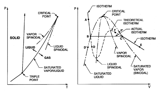
| Figure 1.1 Typical phase diagrams. |
Our discussion will begin with typical phase diagrams, which, though idealized, are relevant to many practical substances. Figure 1.1 shows typical graphs of pressure, p, temperature, T, and specific volume, V, in which the state of the substance is indicated. The triple point is that point in the phase diagram at which the solid, liquid, and vapor states coexist; that is to say the substance has three alternative stable states. The saturated liquid/vapor line (or binodal) extends from this point to the critical point. Thermodynamically it is defined by the fact that the chemical potentials of the two coexisting phases must be equal. On this line the vapor and liquid states represent two limiting forms of a single ``amorphous'' state, one of which can be obtained from the other by isothermal volumetric changes, leading through intermediate but unstable states. To quote Frenkel (1955), ``Owing to this instability, the actual transition from the liquid state to the gaseous one and vice versa takes place not along a theoretical isotherm (dashed line, right, Figure 1.1), but along a horizontal isotherm (solid line), corresponding to the splitting up of the original homogeneous substance into two different coexisting phases...'' The critical point is that point at which the maxima and minima in the theoretical isotherm vanish and the discontinuity disappears.
The line joining the maxima in the theoretical isotherms is called the vapor spinodal line; the line joining the minima is called the liquid spinodal line. Clearly both spinodals end at the critical point. The two regions between the spinodal lines and the saturated (or binodal) lines are of particular interest because the conditions represented by the theoretical isotherm within these regions can be realized in practice under certain special conditions. If, for example, a pure liquid at the state A (Figure 1.1) is depressurized at constant temperature, then several things may happen when the pressure is reduced below that of point B (the saturated vapor pressure). If sufficient numbers of nucleation sites of sufficient size are present (and this needs further discussion later) the liquid will become vapor as the state moves horizontally from B to C, and at pressure below the vapor pressure the state will come to equilibrium in the gaseous region at a point such as E. However, if no nucleation sites are present, the depressurization may lead to continuation of the state down the theoretical isotherm to a point such as D, called a ``metastable state'' since imperfections may lead to instability and transition to the point E. A liquid at a point such as D is said to be in tension, the pressure difference between B and D being the magnitude of the tension. Of course one could also reach a point like D by proceeding along an isobar from a point such as D′ by increasing the temperature. Then an equivalent description of the state at D is to call it superheated and to refer to the difference between the temperatures at D and D′ as the superheat.
In an analogous way one can visualize cooling or pressurizing a vapor that is initially at a state such as F and proceeding to a metastable state such as F′ where the temperature difference between F and F′ is the degree of subcooling of the vapor.
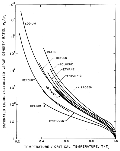
Before proceding with more detail, it is valuable to point out several qualitative features of the liquid state and to remark on its comparison with the simpler crystalline solid or gaseous states. The first and most obvious difference between the saturated liquid and saturated vapor states is that the density of the liquid remains relatively constant and similar to that of the solid except close to the critical point. On the other hand the density of the vapor is different by at least 2 and up to 5 or more orders of magnitude, changing radically with temperature. Since it will also be important in later discussions, a plot of the ratio of the saturated liquid density to the saturated vapor density is included as Figure 1.2 for a number of different fluids. The ratio is plotted against a non-dimensional temperature, θ=T/TC where T is the actual temperature and TC is the critical temperature.
|
| Figure 1.2 Ratio of saturated liquid density to saturated vapor density as a function of temperature for various pure substances. |
Second, an examination of the measured specific heat of the saturated liquid reveals that this is of the same order as the specific heat of the solid except at high temperature close to the critical point. The above two features of liquids imply that the thermal motion of the liquid molecules is similar to that of the solid and involves small amplitude vibrations about a quasi-equilibrium position within the liquid. Thus the arrangement of the molecules has greater similarity with a solid than with a gas. One needs to stress this similarity with a solid to counteract the tendency to think of the liquid state as more akin to the gaseous state than to the solid state because in many observed processes it possesses a dominant fluidity rather than a dominant elasticity. Indeed, it is of interest in this regard to point out that solids also possess fluidity in addition to elasticity. At high temperatures, particularly above 0.6 or 0.7 of the melting temperature, most crystalline solids exhibit a fluidity known as creep. When the strain rate is high, this creep occurs due to the nonisotropic propagation of dislocations (this behavior is not like that of a Newtonian liquid and cannot be characterized by a simple viscosity). At low strain rates, high-temperature creep occurs due simply to the isotropic migration of molecules within the crystal lattice due to the thermal agitation. This kind of creep, which is known as diffusion creep, is analogous to the fluidity observed in most liquids and can be characterized by a simple Newtonian viscosity.
Following this we may ask whether the liquid state possesses an elasticity even though such elasticity may be dominated by the fluidity of the liquid in many physical processes. In both the liquid and solid states one might envisage a certain typical time, tm, for the migration of a molecule from one position within the structure of the substance to a neighboring position; alternatively one might consider this typical time as characterizing the migration of a ``hole'' or vacancy from one position to another within the structure. Then if the typical time, t, associated with the applied force is small compared with tm, the substance will not be capable of permanent deformation during that process and will exhibit elasticity rather than fluidity. On the other hand if t»tm the material will exhibit fluidity. Thus, though the conclusion is overly simplistic, one can characterize a solid as having a large tm and a liquid as having a small tm relative to the order of magnitude of the typical time, t, of the applied force. One example of this is that the earth's mantle behaves to all intents and purposes as solid rock in so far as the propagation of seismic waves is concerned, and yet its fluid-like flow over long geological times is responsible for continental drift.
The observation time, t, becomes important when the phenomenon is controlled by stochastic events such as the diffusion of vacancies in diffusion creep. In many cases the process of nucleation is also controlled by such stochastic events, so the observation time will play a significant role in determining this process. Over a longer period of time there is a greater probability that vacancies will coalesce to form a finite vapor pocket leading to nucleation. Conversely, it is also possible to visualize that a liquid could be placed in a state of tension (negative pressure) for a significant period of time before a vapor bubble would form in it. Such a scenario was visualized many years ago. In 1850, Berthelot (1850) subjected purified water to tensions of up to 50 atmospheres before it yielded. This ability of liquids to withstand tension is very similar to the more familiar property exhibited by solids and is a manifestation of the elasticity of a liquid.
1.4 ILLUSTRATION OF TENSILE STRENGTH
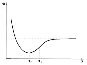
Frenkel (1955) illustrates the potential tensile strength of a pure liquid by means of a simple, but instructive calculation. Consider two molecules separated by a variable distance, s. The typical potential energy, Φ, associated with the intermolecular forces has the form shown in Figure 1.3. Equilibrium occurs at the separation, xo, typically of the order of 10-10m. The attractive force, F, between the molecules is equal to ∂Φ/∂x and is a maximum at some distance, x1, where typically x1/xo is of the order of 1.1 or 1.2. In a bulk liquid or solid this would correspond to a fractional volumetric expansion, ΔV/Vo, of about one-third. Consequently the application of a constant tensile stress equal to that pertinent at x1 would completely rupture the liquid or solid since for x>x1 the attractive force is insufficient to counteract that tensile force. In fact, liquids and solids have compressibility moduli, κ, which are usually in the range of 1010 to 1011 kg/m s2 and since the pressure, p=-κ(ΔV/Vo), it follows that the typical pressure that will rupture a liquid, pT, is -3×10⁹ to -3×10¹⁰ kg/m s2. In other words, we estimate on this basis that liquids or solids should be able to withstand tensile stresses of 3×10⁴ to 3×10⁵ atmospheres! In practice solids do not reach these limits (the rupture stress is usually about 100 times less) because of stress concentrations; that is to say, the actual stress encountered at certain points can achieve the large values quoted above at certain points even when the overall or globally averaged stress is still 100 times smaller. In liquids the large theoretical values of the tensile strength defy all practical experience; this discrepancy must be addressed.
|
| Figure 1.3 Intermolecular potential. |
It is valuable to continue the above calculation one further step (Frenkel 1955). The elastic energy stored per unit volume of the above system is given by κ(ΔV)2/2Vo or |p|ΔVo/2. Consequently the energy that one must provide to pull apart all the molecules and vaporize the liquid can be estimated to be given by |pT|/6 or between 5×10⁸ and 5×10⁹ kg/m s2. This is in agreement with the order of magnitude of the latent heat of vaporization measured for many liquids. Moreover, one can correctly estimate the order of magnitude of the critical temperature, TC, by assuming that, at that point, the kinetic energy of heat motion, kTC per molecule (where k is Boltzmann's constant, 1.38×10⁻²³ kg m2/s2 K) is equal to the energy required to pull all the molecules apart. Taking a typical 1030 molecules per m3, this implies that TC is given by equating the kinetic energy of the thermal motions per unit volume, or 1.38×10⁷×TC, to |pT|/6. This yields typical values of TC of the order of 30→300°K, which is in accord with the order of magnitude of the actual values. Consequently we find that this simplistic model presents a dilemma because though it correctly predicts the order of magnitude of the latent heat of vaporization and the critical temperature, it fails dismally to predict the tensile strength that a liquid can withstand. One must conclude that unlike the latent heat and critical temperature, the tensile strength is determined by weaknesses at points within the liquid. Such weaknesses are probably ephemeral and difficult to quantify, since they could be caused by minute impurities. This difficulty and the dependence on the time of application of the tension greatly complicate any theoretical evaluation of the tensile strength.
As we discussed in section 1.2, the tensile strength of a liquid can be manifest in at least two ways:
- A liquid at constant temperature could be subjected to a decreasing pressure, p, which falls below the saturated vapor pressure, pV. The value of (pV -p) is called the tension, Δp, and the magnitude at which rupture occurs is the tensile strength of the liquid, ΔpC. The process of rupturing a liquid by decrease in pressure at roughly constant liquid temperature is often called cavitation.
- A liquid at constant pressure may be subjected to a temperature, T, in excess of the normal saturation temperature, TS. The value of ΔT=T-TS is the superheat, and the point at which vapor is formed, ΔTC, is called the critical superheat. The process of rupturing a liquid by increasing the temperature at roughly constant pressure is often called boiling.
 | ......(1.1) |
 | ......(1.2) |
In any practical experiment or application weaknesses can typically occur in two forms. The thermal motions within the liquid form temporary, microscopic voids that can constitute the nuclei necessary for rupture and growth to macroscopic bubbles. This is termed homogeneous nucleation. In practical engineering situations it is much commoner to find that the major weaknesses occur at the boundary between the liquid and the solid wall of the container or between the liquid and small particles suspended in the liquid. When rupture occurs at such sites, it is termed heterogeneous nucleation.
In the following sections we briefly review the theory of homogeneous nucleation and some of the experimental results conducted in very clean systems that can be compared with the theory.
In covering the subject of homogeneous nucleation, it is important to remember that the classical treatment using the kinetic theory of liquids allows only weaknesses of one type: the ephemeral voids that happen to occur because of the thermal motions of the molecules. In any real system several other types of weakness are possible. First, it is possible that nucleation might occur at the junction of the liquid and a solid boundary. Kinetic theories have also been developed to cover such heterogeneous nucleation and allow evaluation of whether the chance that this will occur is larger or smaller than the chance of homogeneous nucleation. It is important to remember that heterogeneous nucleation could also occur on very small, sub-micron sized contaminant particles in the liquid; experimentally this would be hard to distinguish from homogeneous nucleation.
Another important form of weaknesses are micron-sized bubbles (microbubbles) of contaminant gas, which could be present in crevices within the solid boundary or within suspended particles or could simply be freely suspended within the liquid. In water, microbubbles of air seem to persist almost indefinitely and are almost impossible to remove completely. As we discuss later, they seem to resist being dissolved completely, perhaps because of contamination of the interface. While it may be possible to remove most of these nuclei from a small research laboratory sample, their presence dominates most engineering applications. In liquids other than water, the kinds of contamination which can occur in practice have not received the same attention.
Another important form of contamination is cosmic radiation. A collision between a high energy particle and a molecule of the liquid can deposit sufficient energy to initiate nucleation when it would otherwise have little chance of occurring. Such, of course, is the principal of the bubble chamber (Skripov 1974). While this subject is beyond the scope of this text, it is important to bear in mind that naturally occurring cosmic radiation could be a factor in promoting nucleation in all of the circumstances considered here.
1.7 HOMOGENEOUS NUCLEATION THEORY
Studies of the fundamental physics of the formation of vapor voids in the body of a pure liquid date back to the pioneering work of Gibbs (Gibbs 1961). The modern theory of homogeneous nucleation is due to Volmer and Weber (1926), Farkas (1927), Becker and Doring (1935), Zeldovich (1943), and others. For reviews of the subject, the reader is referred to the books of Frenkel (1955) and Skripov (1974), to the recent text by Carey (1992) and to the reviews by Blake (1949), Bernath (1952), Cole (1970), Blander and Katz (1975), and Lienhard and Karimi (1981). We present here a brief and simplified version of homogeneous nucleation theory, omitting many of the detailed thermodynamical issues; for more detail the reader is referred to the above literature.
In a pure liquid, surface tension is the macroscopic manifestation of the intermolecular forces that tend to hold molecules together and prevent the formation of large holes. The liquid pressure, p, exterior to a bubble of radius, R, will be related to the interior pressure, pB, by
 | ......(1.3) |
If the temperature, T, is uniform and the bubble contains only vapor, then the interior pressure pB will be the saturated vapor pressure pV(T). However, the exterior liquid pressure, p=pV -2S/R, will have to be less than pV in order to produce equilibrium conditions. Consequently if the exterior liquid pressure is maintained at a constant value just slightly less than pV -2S/R, the bubble will grow, R will increase, the excess pressure causing growth will increase, and rupture will occur. It follows that if the maximum size of vacancy present is RC (termed the critical radius or cluster radius), then the tensile strength of the liquid, ΔpC, will be given by
 | ......(1.4) |
|---|
It is of interest to substitute a typical surface tension, S=0.05 kg/s2, and a critical vacancy or bubble size, RC, comparable with the intermolecular distance of 10-10 m. Then the calculated tensile strength, ΔpC, would be 109 kg/m s2 or 104 atm. This is clearly in accord with the estimate of the tensile strength outlined in section 1.4 but, of course, at variance with any of the experimental observations.
Equation 1.4 is the first of three basic relations that constitute homogeneous nucleation theory. The second expression we need to identify is that giving the increment of energy that must be deposited in the body of the pure liquid in order to create a nucleus or microbubble of the critical size, RC. Assuming that the critical nucleus is in thermodynamic equilibrium with its surroundings after its creation, then the increment of energy that must be deposited consists of two parts. First, energy must be deposited to account for that stored in the surface of the bubble. By definition of the surface tension, S, that amount is S per unit surface area for a total of 4πRC2S. But, in addition, the liquid has to be displaced outward in order to create the bubble, and this implies work done on or by the system. The pressure difference involved in this energy increment is the difference between the pressure inside and outside of the bubble (which, in this evaluation, is ΔpC, given by Equation 1.4). The work done is the volume of the bubble multiplied by this pressure difference, or 4πRC3ΔpC/3, and this is the work done by the liquid to achieve the displacement implied by the creation of the bubble. Thus the net energy, WCR, that must be deposited to form the bubble is
 | ......(1.5) |
 | ......(1.6) |
|---|
The final step in homogeneous nucleation theory is an evaluation of the mechansims by which energy deposition could occur and the probability of that energy reaching the magnitude, WCR, in the available time. Then Equation 1.6 yields the probability of the liquid being able to sustain a tension of ΔpC during that time. In the body of a pure liquid completely isolated from any external radiation, the issue is reduced to an evaluation of the probability that the stochastic nature of the thermal motions of the molecules would lead to a local energy perturbation of magnitude WCR. Most of the homogeneous nucleation theories therefore relate WCR to the typical kinetic energy of the molecules, namely kT (k is Boltzmann's constant) and the relationship is couched in terms of a Gibbs number,
 | ......(1.7) |
A number of expressions have been proposed for the precise form of the relationship between the nucleation rate, J, defined as the number of nucleation events occurring in a unit volume per unit time and the Gibbs number, Gb, but all take the general form
 | ......(1.8) |
 | ......(1.9) |
1.8 COMPARISON WITH EXPERIMENTS
The nucleation rate, J, is given by Equations
1.8, 1.7, 1.6, and
some form for JO, such as Equation
1.9. It varies with temperature in ways that
are important to identify in order to understand the experimental
observations. Consider the tension, ΔpC, which corresponds
to a given nucleation rate, J, according to these equations:
 | ......(1.10) |
This can be used to calculate the tensile strength of the liquid given the temperature, T, knowledge of the surface tension variation with temperature, and other fluid properties, plus a selected criterion defining a specific critical nucleation rate, J. Note first that the most important effect of the temperature on the tension occurs through the variation of the S3 in the numerator. Since S is roughly linear with T declining to zero at the critical point, it follows that ΔpC will be a strong function of temperature close to the critical point because of the S3 term. In contrast, any temperature dependence of JO is almost negligible because it occurs in the argument of the logarithm. At lower temperatures, far from the critical point, the dependence of ΔpC on temperature is weak since S3 varies little, so the tensile strength, ΔpC, will not change much with temperature.
|
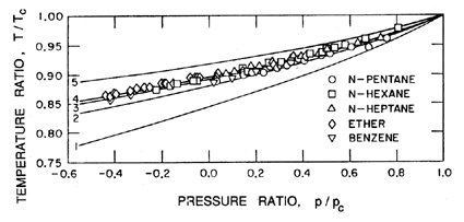 |
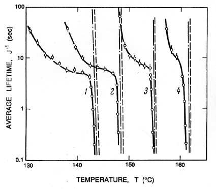
The above remarks addressed the range of temperatures above 0.9TC. We now turn to the differences that occur at lower temperatures. Below about 0.9TC, the superheat limit corresponds to a negative pressure. Indeed, Figure 1.5 includes data down to about -0.4pC (T approximately 0.85TC) and demonstrates that the prediction of the superheat limit from homogeneous nucleation theory works quite well down to this temperature. Lienhard and Karimi (1981) have examined the theoretical limit for water at even lower temperatures and conclude that a more accurate criterion than Gb=11.5 is WCR/kTC=11.5.
One of the reasons for the increasing inaccuracy and uncertainty at lower temperatures is that the homogeneous nucleation theory implies larger and larger tensions, ΔpC, and therefore smaller and smaller critical cluster radii. It follows that almost all of the other nucleation initiators become more important and cause rupture at tensions much smaller than predicted by homogeneous nucleation theory. In water, the uncertainty that was even present for T>0.9TC is increased even further, and homogeneous nucleation theory becomes virtually irrelevant in water at normal temperatures.
1.9 EXPERIMENTS ON TENSILE STRENGTH
Experiments on the tensile strength of water date back to Berthelot (1850) whose basic method has been subsequently used by many investigators. It consists of sealing very pure, degassed liquid in a freshly formed capillary tube under vacuum conditions. Heating the tube causes the liquid to expand, filling the tube at some elevated temperature (and pressure). Upon cooling, rupture is observed at some particular temperature (and pressure). The tensile strength is obtained from these temperatures and assumed values of the compressibility of the liquid. Other techniques used include the mechanical bellows of Vincent (1941) (see also Vincent and Simmonds 1943), the spinning U-tube of Reynolds (1882), and the piston devices of Davies et al. (1956). All these experiments are made difficult by the need to carefully control not only the purity of the liquid but also the properties of the solid surfaces. In many cases it is very difficult to determine whether homogeneous nucleation has occurred or whether the rupture occurred at the solid boundary. Furthermore, the data obtained from such experiments are very scattered.
In freshly drawn capillary tubes, Berthelot (1850) was able to achieve tensions of 50bar in water at normal temperatures. With further refinements, Dixon (1909) was able to get up to 200bar but still, of course, far short of the theoretical limit. Similar scattered results have been reported for water and other liquids by Meyer (1911), Vincent (1941), and others. It is clear that the material of the container plays an important role; using steel Berthelot tubes, Rees and Trevena (1966) were not able to approach the high tensions observed in glass tubes. Clearly, then, the data show that the tensile strength is a function of the contamination of the liquid and the character of the containing surface, and we must move on to consider some of the important issues in this regard.
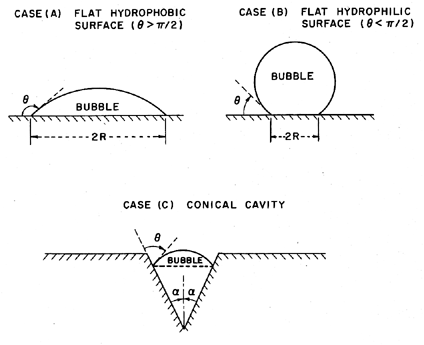
In the case of homogeneous nucleation we considered microscopic voids of radius R, which grow causing rupture when the pressure on the liquid, p, is reduced below the critical value pV -2S/R. Therefore the tensile strength was 2S/R. Now consider a number of analogous situations at a solid/liquid interface as indicated in Figure 1.6.
|
| Figure 1.6 Various modes of heterogeneous nucleation. |
The contact angle at the liquid/vapor/solid intersection is denoted by θ. It follows that the tensile strength in the case of the flat hydrophobic surface is given by 2S sinθ/R where R is the typical maximum dimension of the void. Hence, in theory, the tensile strength could be zero in the limit as θ→π. On the other hand, the tensile strength for a hydrophilic surface is comparable with that for homogeneous nucleation since the maximum dimensions of the voids are comparable. One could therefore conclude that the presence of a hydrophobic surface would cause heterogeneous nucleation and much reduced tensile strength.
Of course, at the microscopic scale with which we are concerned, surfaces are not flat, so we must consider the effects of other local surface geometries. The conical cavity of case (c) is usually considered in order to exemplify the effect of surface geometry. If the half angle at the vertex of this cavity is denoted by α, then it is clear that zero tensile strength occurs at the more realizable value of θ=α+π/2 rather than θ→π. Moreover, if θ>α+π/2, it is clear that the vapor bubble would grow to fill the cavity at pressures above the vapor pressure.
Hence if one considers the range of microscopic surface geometries, then it is not at all surprising that vapor pockets would grow within some particular surface cavities at pressures in the neighborhood of the vapor pressure, particularly when the surface is hydrophobic. Several questions do however remain. First, how might such a vapor pocket first be created? In most experiments it is quite plausible to conceive of minute pockets of contaminant gas absorbed in the solid surface. This is perhaps least likely with freshly formed glass capillary tubes, a fact that may help explain the larger tensions measured in Berthelot tube experiments. The second question concerns the expansion of these vapor pockets beyond the envelope of the solid surface and into the body of the liquid. One could still argue that dramatic rupture requires the appearance of large voids in the body of the liquid and hence that the flat surface configurations should still be applicable on a larger scale. The answer clearly lies with the detailed topology of the surface. If the opening of the cavity has dimensions of the order of 10-5m, the subsequent tension required to expand the bubble beyond the envelope of the surface is only of the order of a tenth of an atmosphere and hence quite within the realm of experimental observation.
It is clear that some specific sites on a solid surface will have the optimum geometry to promote the growth and macroscopic appearance of vapor bubbles. Such locations are called nucleation sites. Furthermore, it is clear that as the pressure is reduced more and more, sites will become capable of generating and releasing bubbles to the body of the liquid. These events are readily observed when you boil a pot of water on the stove. At the initiation of boiling, bubbles are produced at a few specific sites. As the pot gets hotter more and more sites become activated. Hence the density of nucleation sites as a function of the superheat is an important component in the quantification of nucleate boiling.
1.11 NUCLEATION SITE POPULATIONS
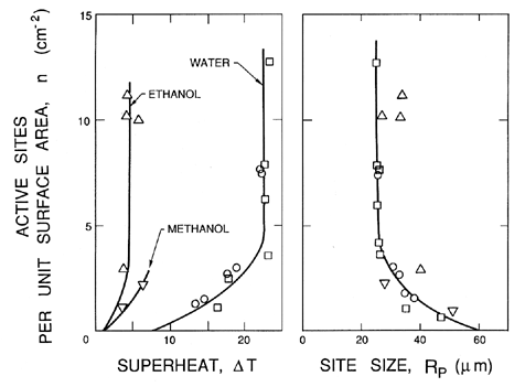
In pool boiling the hottest liquid is in contact with the solid heated wall of the pool, and hence all the important nucleation sites occur in that surface. For the purpose of quantifying the process of nucleation it is necessary to define a surface number density distribution function for the nucleation sites, N(RP), where N(RP)dRP is the number of sites with size between RP and RP+dRP per unit surface area (thus N has units m-3). In addition to this, it is necessary to know the range of sizes brought into operation by a given superheat, ΔT. Characteristically, all sizes greater than RP* will be excited by a tension of βS/RP* where β is some constant of order unity. This corresponds to a critical superheat given by
 | ......(1.11) |
 | ......(1.12) |
|
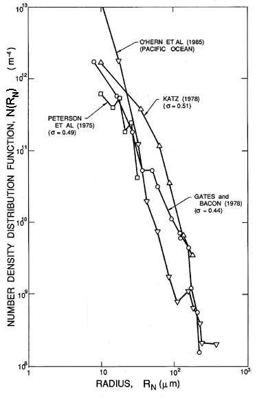
Identification of the nucleation sites involved in the process of cavitation is much more difficult and has sparked a number of controversies in the past. This is because, unlike pool boiling where the largest tensions are experienced by liquid in contact with a heated surface, a reduction in pressure is experienced by the liquid bulk. Consequently very small particles or microbubbles present as contaminants in the bulk of the liquid are also potential nucleation sites. In particular, cavities in micron-sized particles were first suggested by Harvey et al. (1944) as potential ``cavitation nuclei.'' In the context of cavitating flows such particles are called ``free stream nuclei'' to distinguish them from the ``surface nuclei'' present in the macroscopic surfaces bounding the flow. As we shall see later, many of the observations of the onset of cavitation appear to be the result of the excitation of free stream nuclei rather than surface nuclei. Hence there is a need to characterize these free stream nuclei in any particular technological context and a need to control their concentration in any basic experimental study. Neither of these tasks is particularly easy; indeed, it was not until recently that reliable methods for the measurement of free stream nuclei number densities were developed for use in liquid systems of any size. Methods used in the past include the analysis of samples by Coulter counter, and acoustic and light scattering techniques (Billet 1985). However, the most reliable data are probably obtained from holograms of the liquid, which can be reconstructed and microscopically inspected. The resulting size distributions are usually presented as nuclei number density distribution functions, N(RN), such that the number of free stream nuclei in the size range from RN to RN+dRN present in a unit volume is N(RN)dRN (N has units m-4). Illustrated in 1.8 are some typical distributions measured in the filtered and deaerated water of three different water tunnels and in the Pacific Ocean off Los Angeles, California (O'Hern et al. 1985, 1988). Other observations (Billet 1985) produce distributions of similar general shape (roughly N proportional to RN-4 for RN>5μm) but with larger values at higher air contents.
|
| Figure 1.8 Cavitation nuclei number density distribution functions measured by holography in three different water tunnels (Peterson et al. 1975, Gates and Bacon 1978, Katz 1978) at the cavitation numbers, σ, as shown) and in the ocean off Los Angeles, Calif. (O'Hern et al. 1985, 1988). |
It is much more difficult to identify the character of these nuclei. As discussed in the next section, there are real questions as to how small gas-filled microbubbles could exist for any length of time in a body of liquid that is not saturated with that gas. It is not possible to separately assess the number of solid particles and the number of microbubbles with most of the existing experimental techniques. Though both can act as cavitation nucleation sites, it is clear that microbubbles will more readily grow to observable macroscopic bubbles. One method that has been used to count only those nuclei that will cavitate involves withdrawing sample fluid and sucking it through a very small venturi. Nuclei cavitate at the low pressure in the throat and can be counted provided the concentration is small enough so that the events are separated in time. Then the concentrations of nuclei can be obtained as functions of the pressure level in the throat if the flow rate is known. Such devices are known as cavitation susceptibility meters and tend to be limited to concentrations less than 10cm-3 (Billet 1985).
If all of the free stream nuclei were uniform in composition and character, one could conclude that a certain tension Δp would activate all nuclei larger than βΔp/S where β is constant. However, the lack of knowledge of the composition and character of the nuclei as well as other fluid mechanical complications greatly reduces the value of such a statement.
1.12 EFFECT OF CONTAMINANT GAS
Virtually all liquids contain some dissolved gas. Indeed it is virtually impossible to eliminate this gas from any substantial liquid volume. For example, it takes weeks of deaeration to reduce the concentration of air in the water of a tunnel below 3ppm (saturation at atmospheric pressure is about 15ppm). If the nucleation bubble contains some gas, then the pressure in the bubble is the sum of the partial pressure of this gas, pG, and the vapor pressure. Hence the equilibrium pressure in the liquid is p=pV+pG -2S/R and the critical tension is 2S/R - pG. Thus dissolved gas will decrease the potential tensile strength; indeed, if the concentration of gas leads to sufficiently large values of pG, the tensile strength is negative and the bubble will grow at liquid pressures greater than the vapor pressure.
We refer in the above to circumstances in which the liquid is not saturated with gas at the pressure at which it has been stored. In theory, no gas bubbles can exist in equilibrium in a liquid unsaturated with gas but otherwise pure if the pressure is maintained above pV+pG where pG is the equilibrium gas pressure (see Section 2.6). They should dissolve and disappear, thus causing a dramatic increase in the tensile strength of the liquid. While it is true that degassing or high pressure treatment does cause some increase in tensile strength (Keller 1974), the effect is not as great as one would expect. This dilemma has sparked some controversy in the past and at least three plausible explanations have been advanced, all of which have some merit. First is the Harvey nucleus mentioned earlier in which the bubble exists in a crevice in a particle or surface and persists because its geometry is such that the free surface has a highly convex curvature viewed from the fluid so that surface tension supports the high liquid pressure. Second and more esoteric is the possibility of the continuous production of nuclei by cosmic radiation. Third is the proposal by Fox and Herzfeld (1954) of an ``organic skin'' that gives the free surface of the bubble sufficient elasticity to withstand high pressure. Though originally less plausible than the first two possibilities, this explanation is now more widely accepted because of recent advances in surface rheology, which show that quite small amounts of contaminant in the liquid can generate large elastic surface effects. Such contamination of the surface has also been detected by electron microscopy.
1.13 NUCLEATION IN FLOWING LIQUIDS
Perhaps the commonest occurrence of cavitation is in flowing liquid systems where hydrodynamic effects result in regions of the flow where the pressure falls below the vapor pressure. Reynolds (1873) was among the first to attempt to explain the unusual behaviour of ship propellers at the higher rotational speeds that were being achieved during the second half of the ninteenth century. Reynolds focused on the possibility of the entrainment of air into the wakes of the propellor blades, a phenomenon we now term ``ventilation.'' He does not, however, seem to have envisaged the possibility of vapor-filled wakes, and it was left to Parsons (1906) to recognize the role played by vaporization. He also conducted the first experiments on ``cavitation'' (a word suggested by Froude), and the phenomenon has been a subject of intensive research ever since because of the adverse effects it has on performance, because of the noise it creates and, most surprisingly, the damage it can do to nearby solid surfaces.
For the purposes of the present discussion we shall consider a steady, single-phase flow of a Newtonian liquid of constant density, ρL, velocity field, ui(xi), and pressure, p(xi). In all such flows it is convenient to define a reference velocity, U∞, and reference pressure, p∞. In external flows around solid bodies, U∞ and p∞ are conventionally the velocity and pressure of the uniform, upstream flow. The equations of motion are such that changing the reference pressure results in the same uniform change to the pressure throughout the flow field. Thus the pressure coefficient
 | ......(1.13) |
Viscous effects within the flow are characterized by the Reynolds number, Re=ρLU∞ℓ /μL= U∞ℓ /νL where μL and νL are the dynamic and kinematic viscosities of the liquid and ℓ is the characterized length scale. For a given geometry, Cp(xi) and Cpmin are functions only of Re in steady flows. In the idealized case of an inviscid, frictionless liquid, Bernoulli's equation applies and Cp(xi) and Cpmin become dependent only on the geometry of the flow boundaries and not on any other parameters. For purposes of the present discussion, we shall suppose that for the flow geometry under consideration, the value of Cpmin for the single-phase flow is known either from experimental measurement or theoretical calculation.
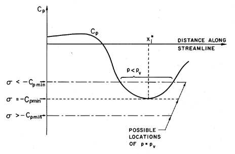
The stage is therefore set to consider what happens in a given flow when either the overall pressure is decreased or the flow velocity is increased so that the pressure at some point in the flow approaches the vapor pressure, pV, of the liquid at the reference temperature, T∞. In order to characterize this relationship, it is conventional to define the cavitation number, σ as
 | ......(1.14) |
|
| Figure 1.9 Schematic of pressure distribution on a streamline. |
In the hypothetical flow of a liquid that cannot withstand any tension and in which vapor bubbles appear instantaneously when p reaches pV, it is clear that
 | ......(1.15) |
1.14 VISCOUS EFFECTS IN CAVITATION INCEPTION
The discussion in the preceding section was deliberately confined to ideal, steady flows. When the flow is also assumed to be inviscid, the value of -Cpmin is a simple positive constant for a given flow geometry. However, when the effects of viscosity are included, Cpmin will be a function of Reynolds number, Re, and even in a steady flow one would therefore expect to observe a dependence of the incipient cavitation number, σi, on the Reynolds number. For convenience, we shall refer to this as the steady viscous effect.
Up to this point we have assumed that the flow and the pressures are laminar and steady. However, most of the flows with which the engineer must deal are not only turbulent but also unsteady. Vortices occur not only because they are inherent in turbulence but also because of both free and forced shedding of vortices. This has important consequences for cavitation inception because the pressure in the center of a vortex may be significantly lower than the mean pressure in the flow. The measurement or calculation of -Cpmin would elicit the value of the lowest mean pressure, while cavitation might first occur in a transient vortex whose core pressure was much lower than the lowest mean pressure. Unlike the residence time factor, this would tend to cause higher values of σi than would otherwise be expected. It would also cause σi to change with Reynolds number, Re. Note that this would be separate from the effect of Re on Cpmin and, to distinguish it, we shall refer to it as the turbulence effect.
In summary, there are a number of reasons for σi to be different from the value of -Cpmin that might be calculated from knowledge of the pressures in the single-phase liquid flow:
- Existence of a tensile strength can cause a reduction in σi.
- Residence time effects can cause a reduction in σi.
- Existence of contaminant gas can cause an increase in σi.
- Steady viscous effect due to dependence of Cpmin on Re can cause σi to be a function of Re.
- Turbulence effects can cause an increase in σi.
Furthermore, the above discussion identifies the parameters that must be controlled or at least measured in systematic experiments on cavitation inception:
- The cavitation number, σ.
- The Reynolds number, Re.
- The liquid temperature, T∞.
- The liquid quality, including the number and nature of the free stream nuclei, the amount of dissolved gas, and the free stream turbulence.
- The quality of the solid, bounding surfaces, including the roughness (since this may affect the hydrodynamics) and the porosity or pit population.
1.15 CAVITATION INCEPTION MEASUREMENTS
To illustrate some of the effects described in the preceding section, we shall attempt to give a brief overview of the extensive literature on the subject of cavitation inception. For more detail, the reader is referred to the reviews by Acosta and Parkin (1975), Arakeri (1979), and Rood (1991), as well as to the book by Knapp, Daily, and Hammitt (1970).
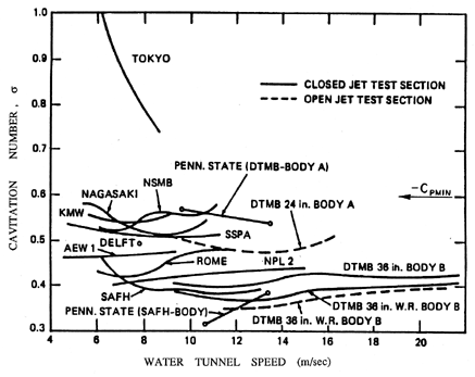
|
| Figure 1.10 The inception numbers measured for the same axisymmetric headform in a variety of water tunnels around the world. Data collected as part of a comparative study of cavitation inception by the International Towing Tank Conference (Lindgren and Johnsson 1966, Johnsson 1969). |
The first effect that we illustrate is that of the uncertainty in the tensile strength of the liquid. It is very difficult to characterize and almost impossible to remove from a substantial body of liquid (such as that used in a water tunnel) all the particles, microbubbles, and contaminant gas that will affect nucleation. This can cause substantial differences in the cavitation inception numbers (and, indeed, the form of cavitation) from different facilities and even in the same facility with differently treated water. The ITTC (International Towing Tank Conference) comparative tests (Lindgren and Johnsson 1966, Johnsson 1969) provided a particularly dramatic example of these differences when cavitation on the same axisymmetric headform (called the ITTC headform) was examined in many different water tunnels around the world. An example of the variation of σi in those experiments is reproduced as Figure 1.10.
|
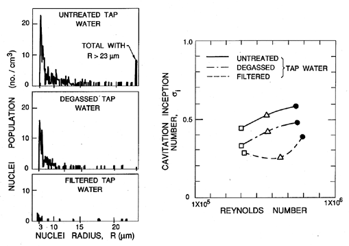
It may be of interest to note that cavitation itself is also a source of nuclei in many facilities. This is because air dissolved in the liquid will tend to come out of solution at low pressures and contribute a partial pressure of air to the contents of any macroscopic cavitation bubble. When that bubble is convected into regions of higher pressure and the vapor condenses, this leaves a small air bubble that only redissolves very slowly, if at all. This unforeseen phenomenon caused great trauma for the first water tunnels, which were modeled directly on wind tunnels. It was discovered that after a few minutes of operating with a cavitating body in the working section, the bubbles produced by the cavitation grew rapidly in number and began to complete the circuit of the facility to return in the incoming flow. Soon the working section was obscured by a two-phase flow. The solution had two components. First, a water tunnel needs to be fitted with a long and deep return leg so that the water remains at high pressure for sufficient time to redissolve most of the cavitation-produced nuclei. Such a return leg is termed a ``resorber.'' Second, most water tunnel facilities have a ``deaerator'' for reducing the air content of the water to 20 to 50% of the saturation level. These comments serve to illustrate the fact that N(RN) in any facility can change according to the operating condition and can be altered both by deaeration and by filtration.
One of the consequences of the effect of cavitation itself on the nuclei population in a facility is that the cavitation number at which cavitation disappears when the pressure is raised may be different from the value of the cavitation number at which it appeared when the pressure was decreased. The first value is termed the ``desinent'' cavitation number and is denoted by σd to distinguish it from the inception number, σi. The difference in these values is termed ``cavitation hysteresis'' (Holl and Treaster 1966).
One of the additional complications is the subjective nature of the judgment that cavitation has appeared. Visual inspection is not always possible, nor is it very objective since the number of events (single bubble growth and collapse) tends to increase gradually over a range of cavitation numbers. If, therefore, one made a judgment based on a certain event rate, it is inevitable that the inception cavitation number would increase with nuclei population. Experiments have found that the production of noise is a simpler and more repeatable measure of inception than visual observation. While still subject to the variations with nuclei population discussed above, it has the advantage of being quantifiable.
Most of the data of Figure 1.8 is taken from water tunnel water that has been somewhat filtered and degassed or from the ocean, which is surprisingly clean. Thus there are very few nuclei with a size greater than 100μm. On the other hand, there are many hydraulic applications in which the water contains much larger gas bubbles. These can then grow substantially as they pass through a region of low pressure in the pump or other hydraulic device, even though the pressure is everywhere above the vapor pressure. Such a phenomenon is called ``pseudo-cavitation.'' Though a cavitation inception number is not particularly relevant to such circumstances, attempts to measure σi under these circumstances would clearly yield values much larger than -Cpmin.
On the other hand, if the liquid is quite clean with only very small nuclei, the tension that this liquid can sustain would mean that the minimum pressure would have to fall well below pV for inception to occur. Then σi would be much smaller than -Cpmin. Thus it is clear that the quality of the water and its nuclei could cause the cavitation inception number to be either larger or smaller than -Cpmin.
1.16 CAVITATION INCEPTION DATA
Though much of the inception data in the literature is deficient in the sense that the nuclei population and character are unknown, it is nevertheless of value to review some of the important trends in that data base. In doing so we could be reassured that each investigator probably applied a consistent criterion in assessing cavitation inception. Therefore, though the data from different investigators and facilities may be widely scattered, one would hope that the trends exhibited in a particular research project would be qualitatively significant.
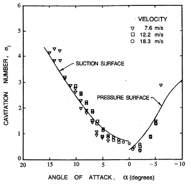
|
| Figure 1.12 Cavitation inception characteristics of a NACA 4412 hydrofoil (Kermeen 1956). |
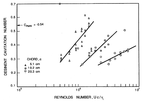
Consider first the inception characteristics of a single hydrofoil as the angle of attack is varied. The data of Kermeen (1956), obtained for a NACA 4412 hydrofoil, is reproduced in Figure 1.12. At positive angles of attack the regions of low pressure and cavitation inception will occur on the suction surface; at negative angles of attack these phenomena will shift to the pressure surface. Furthermore, as the angle of attack is increased in either direction, the value of -Cpmin will increase, and hence the inception cavitation number will also increase. As we will discuss in the next section, the scaling of cavitation inception with changes in the size and speed of the hydraulic device can be an important issue, particularly when scaling the results from model-scale water tunnel experiments to prototypes as is necessary, for example, in developing ship propellers. Typical data on cavitation inception for a single hydrofoil (Holl and Wislicenus 1961) is reproduced in Figure 1.13. Data for three different sizes of 12% Joukowski hydrofoil (at zero angle of attack) were obtained at different speeds. They were plotted against Reynolds number in the hope that this would reduce the data to a single curve. The fact that this did not occur demonstrates that there is a size or speed effect separate from that due to the Reynolds number. It seems reasonable to suggest that the missing parameter is the ratio of the nuclei size to chord length; however, in the absence of information on the nuclei, such conclusions are purely speculative.
|
Turbulence affects cavitation inception since a nucleus may find itself in the core of a vortex where the pressure level is lower than the mean. It could therefore cavitate when it might not do so under the influence of the mean pressure level. Thus turbulence may promote cavitation, but one must allow for the fact that it may alter the global pressure field by altering the location of flow separation. These complicated viscous effects on cavitation inception were first examined in detail by Arakeri and Acosta (1974) and Gates and Acosta (1978) (see also Arakeri 1979). The implications for cavitation inception in the highly turbulent environment of many internal flows such as occur in pumps have yet to be examined in detail.
1.17 SCALING OF CAVITATION INCEPTION
The complexity of the issues raised in the last section helps to explain why serious questions remain as to how to scale cavitation inception. This is perhaps one of the most troublesome issues a hydraulic engineer must face. Model tests of a ship's propeller or large pump-turbine may allow the designer to accurately estimate the noncavitating performance of the device. However, he will not be able to place anything like the same confidence in his ability to scale the cavitation inception data.
Consider the problem in more detail. Changing the size of the device will alter not only the residence time effect but also the Reynolds number. Furthermore, the nuclei will now be a different size relative to the device than in the model. Changing the speed in an attempt to maintain Reynolds number scaling may only confuse the issue by further alterating the residence time. Moreover, changing the speed will also change the cavitation number. To recover the modeled condition, one must then change the pressure level, which may alter the nuclei content. There is also the issue of what to do about the surface roughness in the model and in the prototype.
The other issue of scaling that arises is how to anticipate the cavitation phenomena in one liquid based on data obtained in another. It is clearly the case that the literature contains a great deal of data on water. Data on other liquids are quite meager. Indeed, I have not located any nuclei number distributions for a fluid other than water. Since the nuclei play such a key role, it is not surprising that our current ability to scale from one liquid to another is quite tentative.
It would not be appropriate to leave this subject without emphasizing that most of the remarks in the last two sections have focused on the inception of cavitation. Once cavitation has become established, the phenomena that occur are much less sensitive to special factors such as the nuclei content. Hence the scaling of developed cavitation can proceed with much more confidence than the scaling of cavitation inception. This is not, however, of much solace to the engineer charged with avoiding cavitation completely.
- Acosta, A.J. and Parkin, B.R. (1975). Cavitation inception---a selective review. J. Ship Res., 19, 193--205.
- Arakeri, V.H. (1979). Cavitation inception. Proc. Indian Acad. Sci., C2, Part 2, 149--177.
- Arakeri, V.H. and Acosta, A.J. (1974). Viscous effects in the inception of cavitation on axisymmetric bodies. ASME J. Fluids Eng., 95, No. 4, 519--528.
- Arndt, R.E.A. and Ippen, A.T. (1968). Rough surface effects on cavitation inception. ASME J. Basic Eng., 90, 249--261.
- Becker, R. and Doring, W. (1935). The kinetic treatment of nuclear formation in supersaturated vapors. Ann. Phys., 24, 719 and 752.
- Bernath, L. (1952). Theory of bubble formation in liquids. Ind. Eng. Chem., 44, No. 6, 1310--1313.
- Berthelot, M. (1850). Sur quelques phenomenes de dilation forcee de liquides. Ann. de Chimie et de Physique, 30, 232--237.
- Billet, M.L. (1985). Cavitation nuclei measurement---a review. Proc. 1985 ASME Cavitation and Multiphase Flow Forum, 31--38.
- Blake, F.G. (1949). The tensile strength of liquids; a review of the literature. Harvard Acou. Res. Lab. Rep. TM9.
- Blander, M. and Katz, J.L. (1975). Bubble nucleation in liquids. AIChE Journal, 21, No. 5, 833--848.
- Carey, V.P. (1992). Liquid-vapor phase-change phenomena. Hemisphere Publ. Co.
- Cole, R. (1970). Boiling nucleation. Adv. Heat Transfer, 10, 86--166.
- Davies, R.M., Trevena, D.H., Rees, N.J.M., and Lewis, G.M. (1956). The tensile strength of liquids under dynamic stressing. Proc. N.P.L. Symp. on Cavitation in Hydrodynamics.
- Dixon, H.H. (1909). Note on the tensile strength of water. Sci. Proc. Royal Dublin Soc., 12, (N.S.), 60 (see also 14, (N.S.), 229, (1914)).
- Eberhart, J.G. and Schnyders, M.C. (1973). Application of the mechanical stability condition to the prediction of the limit of superheat for normal alkanes, ether, and water. J. Phys. Chem., 77, No. 23, 2730--2736.
- Farkas, L. (1927). The velocity of nucleus formation in supersaturated vapors. J. Physik Chem., 125, 236.
- Fox, F.E. and Herzfeld, K.F. (1954). Gas bubbles with organic skin as cavitation nuclei. J. Acoust. Soc. Am., 26, 984--989.
- Frenkel, J. (1955). Kinetic theory of liquids. Dover, New York.
- Gates, E.M. and Acosta, A.J. (1978). Some effects of several free stream factors on cavitation inception on axisymmetric bodies. Proc. 12th Naval Hydrodyn. Symp., Wash. D.C., 86--108.
- Gates, E.M. and Bacon, J. (1978). Determination of cavitation nuclei distribution by holography. J. Ship Res., 22, No. 1, 29--31.
- Gibbs, W. (1961). The Scientific Papers, Vol. 1. Dover Publ. Inc., NY.
- Griffith, P. and Wallis, J.D. (1960). The role of surface conditions in nucleate boiling. Chem. Eng. Prog. Symp., Ser. 56, 30, 49.
- Harvey, E.N., Barnes, D.K. , McElroy, W.D., Whiteley, A.H., Pease, D.C., and Cooper, K.W. (1944). Bubble formation in animals. I, Physical factors. J. Cell. and Comp. Physiol., 24, No. 1, 1--22.
- Holl, J.W. and Wislicenus, G.F. (1961). Scale effects on cavitation. ASME J. Basic Eng., 83, 385--398.
- Holl, J.W. and Treaster, A.L. (1966). Cavitation hysteresis. ASME J. Basic Eng., 88, 199--212.
- Johnsson, C.A. (1969). Cavitation inception on headforms, further tests. Proc. 12th Int. Towing Tank Conf., Rome, 381--392.
- Katz, J. (1978). Determination of solid nuclei and bubble distributions in water by holography. Calif.Inst. of Tech., Eng. and Appl. Sci. Div. Rep. No. 183--3.
- Katz, J., Gowing, S., O'Hern, T., and Acosta, A.J. (1984). A comparitive study between holographic and light-scattering techniques of microbubble detection. Proc. IUTAM Symp. on Measuring Techniques in Gas-Liquid Two-Phase Flows, 41--66.
- Keller, A.P. (1974). Investigations concerning scale effects of the inception of cavitation. Proc. I.Mech.E. Conf. on Cavitation, 109--117.
- Kermeen, R.W. (1956). Water tunnel tests of NACA 4412 and Walchner profile 7 hydrofoils in non-Cavitating and cavitating Flows. Calif. Inst. of Tech. Hydro. Lab. Rep. 47-5.
- Knapp, R.T., Daily, J.W., and Hammitt, F.G. (1970). Cavitation. McGraw-Hill, New York.
- Lienhard, J.H. and Karimi, A. (1981). Homogeneous nucleation and the spinodal line. ASME J. Heat Transfer, 103, 61--64.
- Lindgren, H. and Johnsson, C.A. (1966). Cavitation inception on headforms, ITTC comparitive experiments. Proc. 11th Towing Tank Conf. Tokyo, 219--232.
- Meyer, J. (1911). Zur Kenntnis des negativen Druckes in Flüssigkeiten. Abhandl. Dent. Bunsen Ges., III, No. 1; also No. 6.
- O'Hern, T.J., Katz, J., and Acosta, A.J. (1985). Holographic measurements of cavitation nuclei in the sea. Proc. ASME Cavitation and Multiphase Flow Forum, 39--42.
- O'Hern, T., d'Agostino, L., and Acosta, A.J. (1988). Comparison of holographic and Coulter counter measurements of cavitation nuclei in the ocean. ASME J. Fluids Eng., 110, 200--207.
- Parsons, C.A. (1906). The steam turbine on land and at sea. Lecture to the Royal Institution, London.
- Peterson, F.B., Danel, F., Keller, A.P., and Lecoffre, Y. (1975). Comparitive measurements of bubble and particulate spectra by three optical methods. Proc. 14th Int. Towing Tank Conf.
- Rees, E.P. and Trevena, D.H. (1966). Cavitation thresholds in liquids under static conditions. Proc. ASME Cavitation Forum, 12 (see also (1967), 1).
- Reynolds, O. (1873). The causes of the racing of the engines of screw steamers investigated theoretically and by experiment. Trans. Inst. Naval Arch., 14, 56--67.
- Reynolds, O. (1882). On the internal cohesion of liquids and the suspension of a column of mercury to a height of more than double that of the barometer. Mem. Manchester Lit. Phil. Soc., 7, 3rd Series, 1.
- Rood, E.P. (1991). Mechanisms of cavitation inception---review. ASME J. Fluids Eng., 113, 163--175.
- Skripov, V.P. (1974). Metastable Liquids. John Wiley and Sons.
- Vincent, R.S. (1941). The measurement of tension in liquids by means of a metal bellows. Proc. Phys. Soc. (London), 53, 126--140.
- Vincent, R.S. and Simmonds, G.H. (1943). Examination of the Berthelot method of measuring tension in liquids. Proc. Phys. Soc. (London), 55, 376--382.
- Volmer, M. and Weber, A. (1926). Keimbildung in übersättigten Gebilden. Zeit. Physik. Chemie, 119, 277--301.
- Zeldovich, J.B. (1943). On the theory of new phase formation: cavitation. Acta Physicochimica, URSS, 18, 1--22.
Last updated 12/1/00.
Christopher E. Brennen